Eureka AIR delivers breakthrough ideas for toughest innovation challenges, trusted by R&D personnel around the world.

A high-efficiency cleaning device for laboratory test tubes

A cleaning device and the technology of the laboratory, which is applied in the field of high-efficiency cleaning devices for test tubes in the laboratory, can solve the problems of reduced cleaning efficiency, waste of manpower, secondary pollution, etc., and achieve the effect of improving cleaning efficiency and reducing the number of clamping times

Active Publication Date: 2021-08-31
THE AFFILIATED HOSPITAL OF QINGDAO UNIV
View PDF7 Cites 0 Cited by
  • Summary
  • Abstract
  • Description
  • Claims
  • Application Information

AI Technical Summary

Problems solved by technology

[0002] The laboratory needs to do a lot of tests. Test tubes are commonly used medical testing instruments in the laboratory. A large number of contaminated test tubes are produced every day. The inner walls of the contaminated test tubes are stained with liquid or adhered to solid substances, which need to be cleaned for the next time. In use, the existing cleaning device can only re-clamp the test tube to clean the outer wall of the test tube after cleaning the inside of the test tube because of the clamping. It cannot be cleaned at the same time, which greatly reduces the cleaning efficiency. It is also a waste of manpower when switching the clamping position, and it is easy to cause secondary pollution during the switching process

Method used


Image

  • A high-efficiency cleaning device for laboratory test tubes
  • A high-efficiency cleaning device for laboratory test tubes
  • A high-efficiency cleaning device for laboratory test tubes

Examples


Embodiment Construction

[0028] In order to make the technical means, creative features, goals and effects achieved by the present invention easy to understand, the present invention will be further described below in conjunction with specific embodiments.

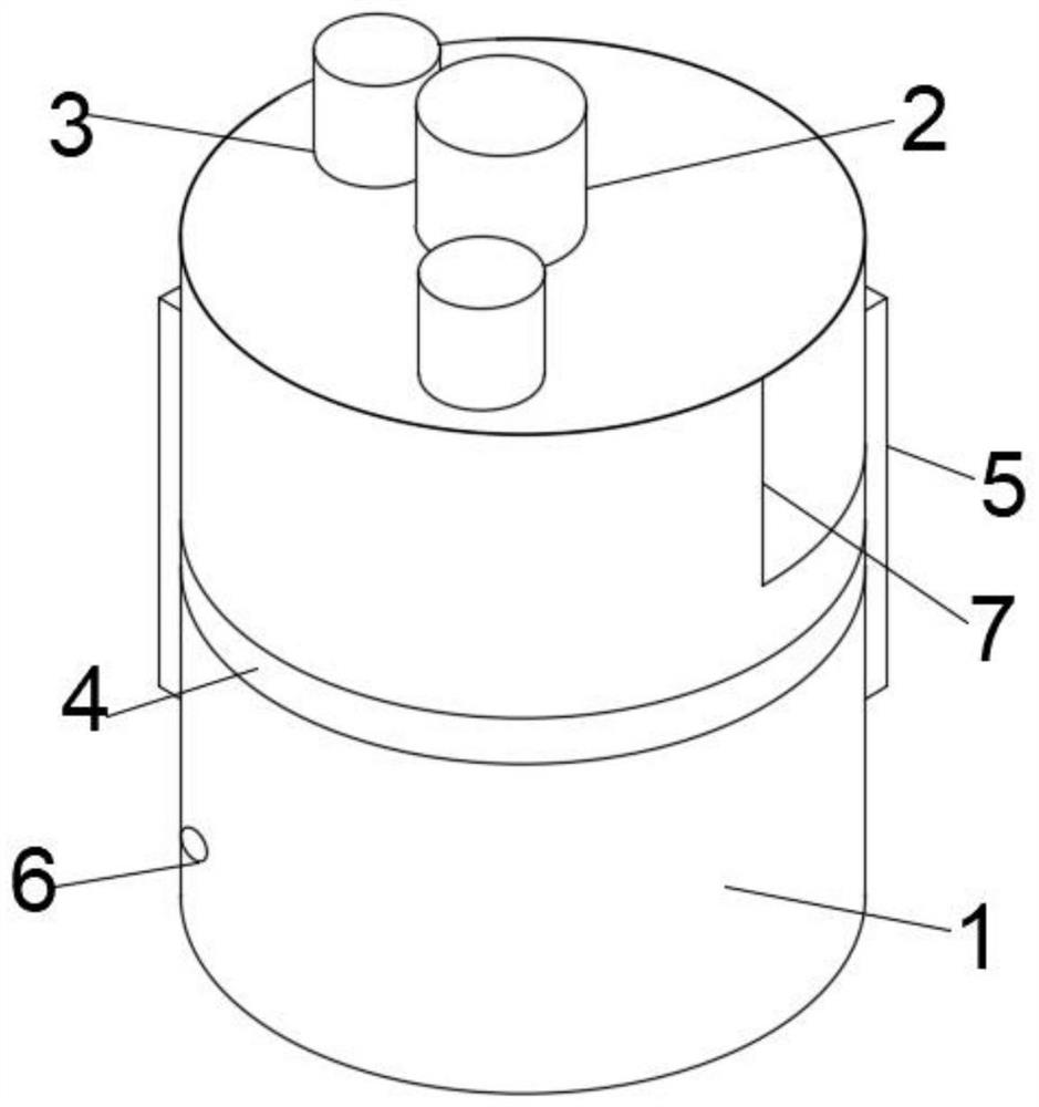
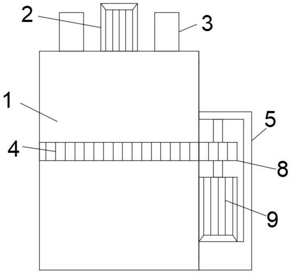
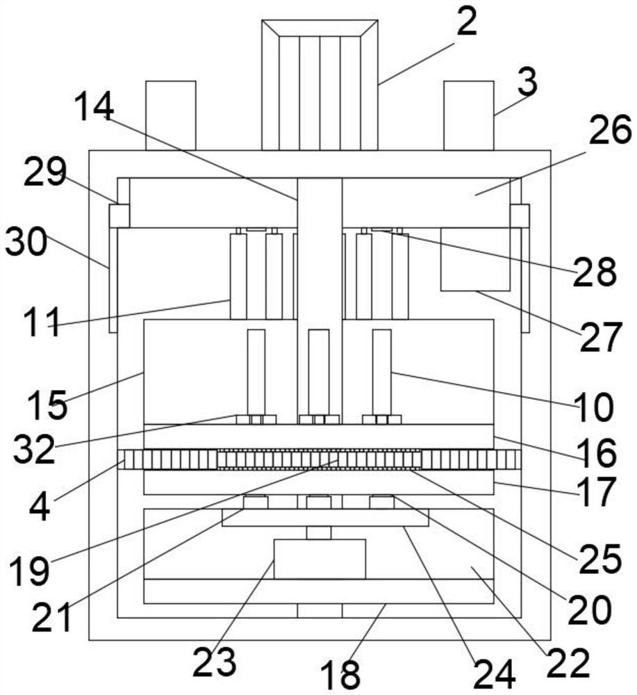
[0029] Such as Figure 1-10As shown, a high-efficiency cleaning device for laboratory test tubes includes a cylinder body 1 with a switch door 7, and the eccentric position inside the cylinder body 1 is movably connected with a rotating shaft 14 driven by a first motor 2, and the rotating shaft 14 is connected from above to A first plate body 16, a second plate body 17 and a third plate body 18 are provided in sequence from bottom to bottom. A plurality of spacers 32 are arranged on the first plate body 16, and inner wall cleaning is provided in the middle of the spacer blocks 32. device, the inner wall cleaning device passes through the first plate body 16 and the second plate body 17 is movably connected, the outer side of the inner wall cleanin...


PUM


Abstract

The invention discloses a high-efficiency cleaning device for laboratory test tubes, which comprises a cylinder body. The eccentric position inside the cylinder body is movably connected with a rotating shaft driven by a first motor. The rotating shaft is sequentially provided with a first plate body and a second plate body from top to bottom. and the third plate, the first plate is provided with a plurality of pads, the middle of the pad is provided with an inner wall cleaning device, the outer side of the inner wall cleaning device is engaged with a second transmission part, and the cylinder is provided with a first transmission part, the cylinder The outer side of the body is provided with a first transmission device, the third plate body is provided with a first water delivery device connected with the inner wall cleaning device, the upper end of the cylinder is provided with a movable box, the movable box is provided with an outer wall cleaning device, and the movable box is provided with a There is a second transmission device and a second water delivery device for water supply, and a rotating block is movable in the middle of the lower end surface of the outer wall cleaning device. In the present invention, by setting the outer wall cleaning device and the inner wall cleaning device, the inner and outer walls of the test tube can be cleaned at the same time, the times of clamping are reduced, and the cleaning efficiency is improved.

Description

technical field [0001] The invention relates to the field of laboratory auxiliary equipment, in particular to a high-efficiency cleaning device for laboratory test tubes. Background technique [0002] The laboratory needs to do a lot of tests. Test tubes are commonly used medical testing instruments in the laboratory. A large number of contaminated test tubes are produced every day. The inner walls of the contaminated test tubes are stained with liquid or adhered to solid substances, which need to be cleaned for the next time. In use, the existing cleaning device can only re-clamp the test tube to clean the outer wall of the test tube after cleaning the inside of the test tube because of the clamping. It cannot be cleaned at the same time, which greatly reduces the cleaning efficiency. It is also a waste of manpower when switching the clamping position, and it is easy to cause secondary pollution during the switching process. Contents of the invention [0003] The main pu...

Claims


Application Information

Patent Timeline
Patent Type & Authority Patents(China)
IPC IPC(8): B08B9/36B08B9/28B08B13/00
CPCB08B9/28B08B9/36B08B13/00
Inventor 张甲由赵少芹
Owner THE AFFILIATED HOSPITAL OF QINGDAO UNIV
Why Eureka
Eureka Blog
Learn More