Dynamic control method and apparatus for sewage disposal

A dynamic control and sewage treatment technology, applied in water/sewage multi-stage treatment, biological water/sewage treatment, water/sludge/sewage treatment, etc., can solve wasteful energy consumption, accurate control, low-load sludge bulking, etc. problems, to achieve the effect of reducing labor intensity, reducing control steps, and reducing operating energy consumption

Inactive Publication Date: 2009-03-04
闫长军 +1
View PDF0 Cites 29 Cited by
  • Summary
  • Abstract
  • Description
  • Claims
  • Application Information

AI Technical Summary

Problems solved by technology

[0004] 1. Since the existing sewage treatment system cannot adjust and control in real time according to the water inflow, when the inflow and water quality change values ​​deviate greatly from the preset values, the system will not be able to accurately carry out the treatment process. Therefore, the water quality in the discharged water cannot meet the standard, or due to excessive aeration, it leads to waste of energy consumption, and may also cause low-load sludge bulking
[0005] 2. Since the existing sewage treatment system cannot perform real-time adjustment and control according to the changing parameters in the water quality, the operation and management personnel cannot timely understand the changes in the total water inflow and water quality, so that they cannot be accurately controlled, which also caused The quality of effluent water is not up to standard, and renewable water resources are wasted
[0006] 3. The distribution and supply effect of aeration volume in most sewage treatment plants is not ideal. The control of dissolved oxygen concentration lags behind, has low precision, large fluctuations, high energy consumption and directly affects the treatment effect; while aeration power consumption accounts for the total of sewage treatment plants. About 80% of the operating cost, so ineffective aeration should be avoided to save energy

Method used


Image

  • Dynamic control method and apparatus for sewage disposal
  • Dynamic control method and apparatus for sewage disposal

Examples


Embodiment Construction

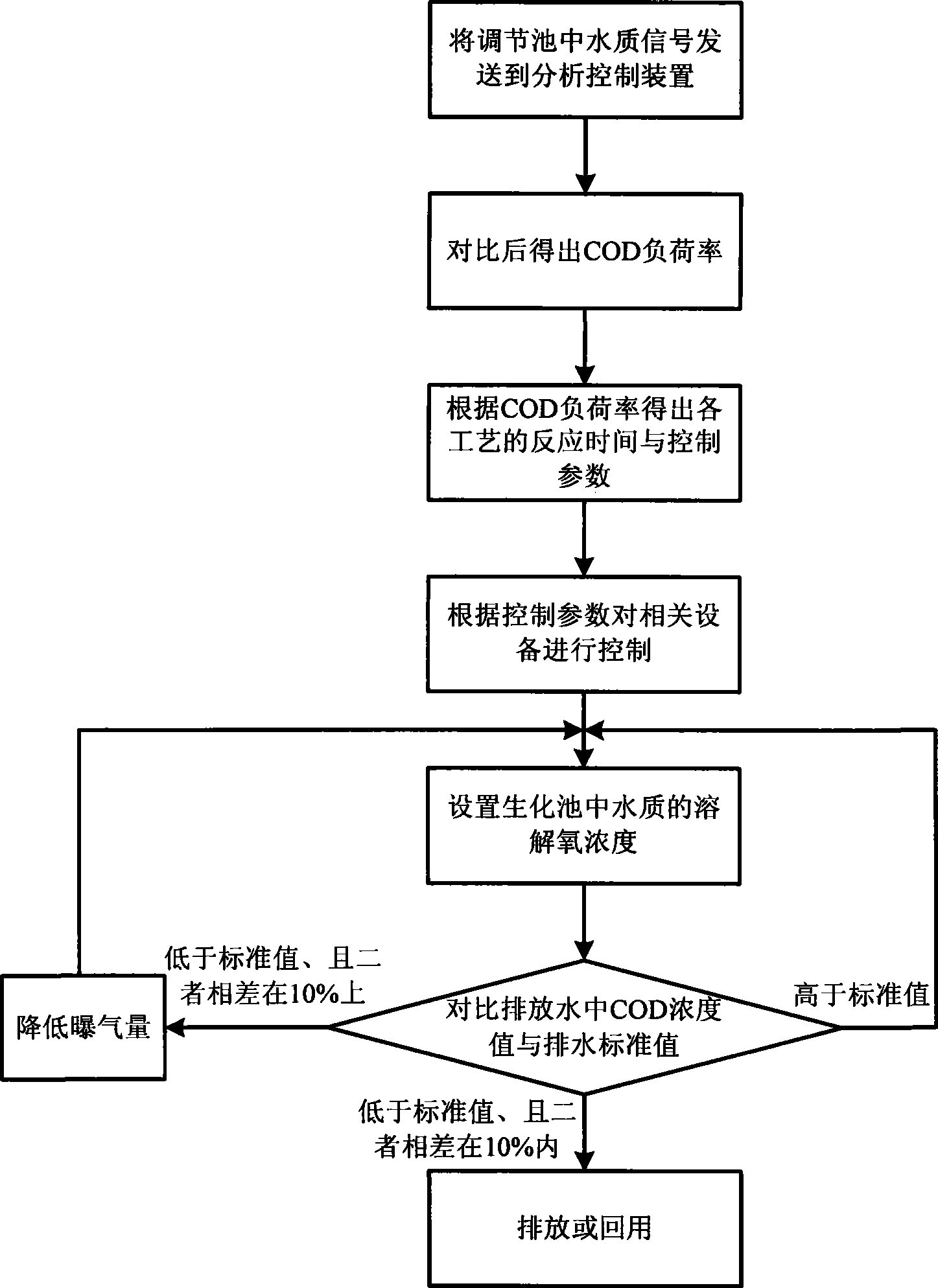
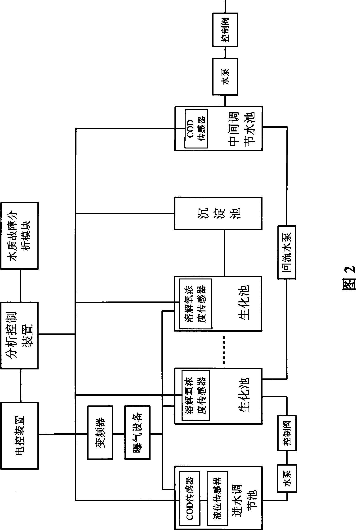
[0033] A dynamic control method for sewage treatment provided by the present invention includes a water inlet adjustment pool, a plurality of biochemical pools and an intermediate adjustment pool. The method includes the following steps:

[0034] (1) After the sewage is injected into the water inlet adjustment tank, the COD signal and liquid level signal data are input into the analysis control device through the COD concentration sensor and the liquid level sensor;

[0035] (2) The COD load rate is obtained after comparing with the required value of terminal effluent;

[0036] (3) According to the COD load rate obtained in the step (2), the water quality treatment capacity, the aeration rate and the response time and control parameters of each process in the unit time of the sewage treatment system are calculated;

[0037] (4) According to the control parameter obtained in the step (3), the sewage in the water inlet regulating tank is introduced in the biochemical tank by a w...


PUM


Abstract

The invention relates to a dynamic control method for sewage treatment, which comprises the following steps: adopting sensors to input the COD signal and the liquid-level signal to an analysis control device; calculating the COD load rate after the comparison with the terminal effluent requirement; carrying out the biochemical treatment of sewage according to the reaction times of the relevant procedures and the control parameters which are calculated on basis of the COD load rate; comparing the COD value of the discharged or reclaim water body with the standard value; and discharging or reclaiming if the COD value meets the standard and otherwise carrying out the secondary treatment. The devices used in dynamic control method further include COD concentration sensors, liquid level sensors and dissolved oxygen concentration sensors, which are arranged inside a water inlet regulating pond, a biochemical pond and an intermediate regulating pond respectively. The sensors are connected with the analysis control device. The dynamic control method integrally adopts the dynamic control mode, can accurately control the water treatment capacity and the aeration capacity in unit time, and ensure that the water discharge meets the water quality standard completely on the premise of the minimal energy consumption.

Description

technical field [0001] The invention relates to the technical field of sewage treatment, in particular to a dynamic control method and device for sewage treatment. Background technique [0002] With the development of modern industry and agriculture, a large amount of industrial, agricultural and domestic wastes are produced and released into the environment, causing the environment to be polluted. Due to the presence of a large number of toxic and harmful substances in the waste, it seriously affects the normal life of human beings. with production. Among them, water pollution is one of the main pollution. Recently, more than 420 billion cubic meters of sewage are discharged into rivers, lakes and seas in the world every year, and about 5.5 trillion cubic meters of fresh water are polluted, which is equivalent to more than 14% of the total global runoff. Over the years, researchers have applied methods including biological treatment, chemical treatment, thermal treatment,...

Claims


Application Information

Patent Timeline
Patent Type & Authority Applications(China)
IPC IPC(8): C02F9/14C02F3/12C02F3/30
CPCY02W10/10
Inventor 闫长军张锐
Owner 闫长军
Why Eureka
Try Eureka