Copper strip machining process

A processing technology, copper strip technology, applied in the field of copper strip processing technology, can solve problems such as time-consuming, not easy to operate, large gap between copper strips, etc., to increase the copper strip winding speed and increase the copper strip winding volume , the effect of saving operation time

Active Publication Date: 2020-07-24
ZHAOQING CITY ZHONGNANTIAN IND CO LTD
View PDF10 Cites 0 Cited by
  • Summary
  • Abstract
  • Description
  • Claims
  • Application Information

AI Technical Summary

Problems solved by technology

[0003] When the existing copper strip winding machine is in use, the copper strip reel needs to be set on the fan-shaped support plate first, then the pressure rod is placed on the fan-shaped support plate, and the pressure rod is pushed to the copper tape reel, and finally the bolt is used to Fix the pressure rod so that the pressure rod can limit the copper tape reel during the subsequent winding process of the copper tape. However, due to the complicated way of fixing the pressure rod, the operation is not easy enough, so that the operator will be confused when replacing the copper tape reel. It takes a lot of time, and during the copper strip winding process, the gap between the copper strips is too large, which can easily lead to the phenomenon of bending of the copper strip during the winding process, resulting in the problem of low copper strip winding efficiency. For this reason, we propose A kind of copper strip processing technology

Method used


Image

  • Copper strip machining process
  • Copper strip machining process
  • Copper strip machining process

Examples


Embodiment approach

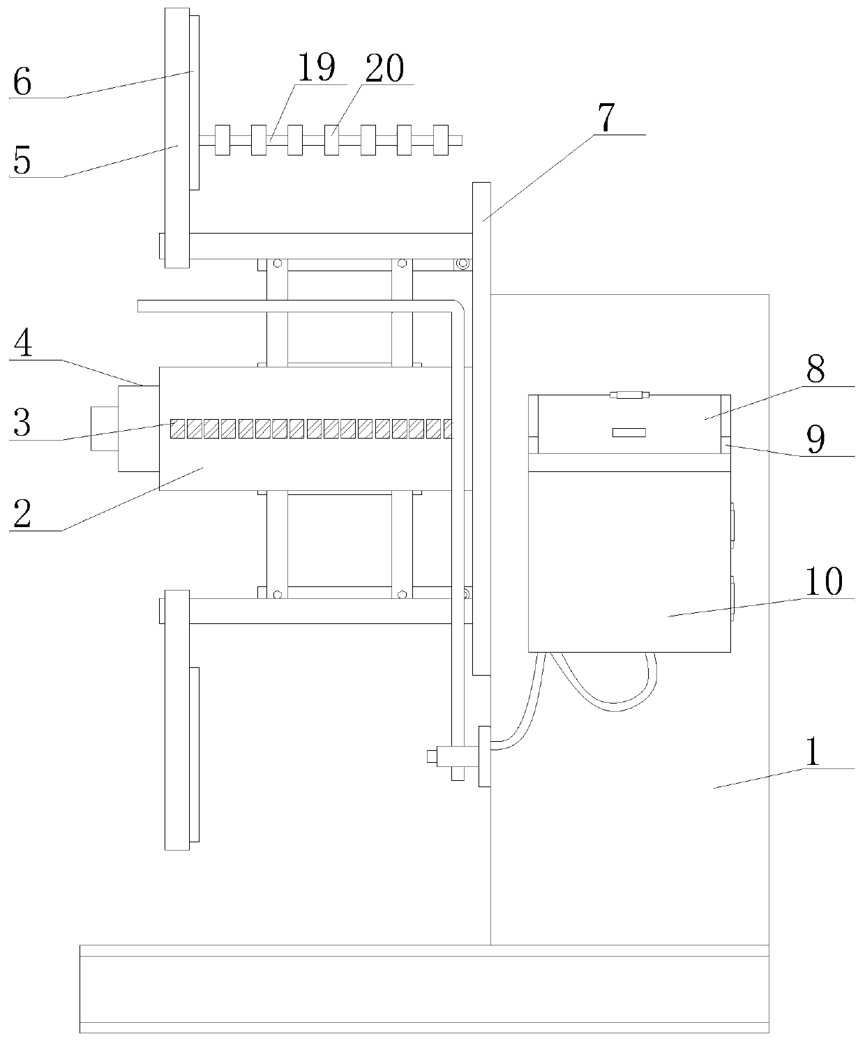
[0038] As an embodiment of the present invention, the front surface of the body 1 is provided with an operation box 10, and the top surface of the operation box 10 is provided with an operation panel, the top of the operation box 10 is connected with a transparent cover 8, and the transparent cover 8 It is a transparent material member; when working, the operation panel on the top of the operation box 10 can be blocked by the transparent cover 8, thereby avoiding the external dust directly falling on the surface of the operation panel, causing the problem of difficult follow-up cleaning. Play a certain protective role to avoid the problem of contact between external objects and the buttons on the operation panel, and because the transparent cover 8 is a transparent material component, the operator can pass through the transparent cover 8 to the buttons on the operation panel during daily use. The presentation status is observed.

[0039] As an embodiment of the present inventi...


PUM


Abstract

The invention belongs to the technical field of copper strip machining, and particularly relates to a copper strip machining process. The process comprises a machine body; a turn table is arranged onthe surface of one side of the machine body; a central shaft is arranged at the center of the surface of one side of the turn table; four fan-shaped bracing plates are arranged on the surface of one side of the turn table; and two pressing rods are arranged in symmetry on one side of the turn table. When a copper strip disc is sleeved on the surfaces of the fan-shaped bracing plates, the two pressing rods are sleeved on the surfaces of two random symmetrical fan-shaped bracing plates, and the pressing rods are then pushed to one side of the copper strip disc and compact the copper strip disc via a squeezing plate, so the copper strip disc can be limited. When the copper strip disc that rolls up a cooper strip is required to be taken down afterwards, the copper strip disc can be successfully taken down by upwardly lifting a lifting rod from the inside of a rectangular gap and taking down the pressing rods. The whole process is simple and convenient, and good effect of limiting the copper strip disc can be realized. Compared with complicated operation of an original device, the process can save the operation time of an operator by a large percentage.

Description

technical field [0001] The invention belongs to the technical field of copper strip processing, in particular to a copper strip processing technology. Background technique [0002] Copper strip is a metal component, mainly used in the production of electrical components, lamp caps, battery caps, buttons, seals, connectors, mainly used for electrical conduction, heat conduction, corrosion resistance equipment, etc., and the processing process of copper strip includes feeding , Uncoiling, leveling, slitting, buffering, tension, winding and many other processes, among which the winding process is the last process in the copper strip processing process, and it is also very important. Most of them use a copper strip winding machine , this copper strip winding machine can carry out the final winding of the copper strip. [0003] When the existing copper strip winding machine is in use, the copper strip reel needs to be set on the fan-shaped support plate first, then the pressure ...

Claims


Application Information

Patent Timeline
IPC IPC(8): B21C47/02B21C47/24B21C47/34B08B17/04
CPCB21C47/02B21C47/24B21C47/34B08B17/04
Inventor 方振钋薛继纲
Owner ZHAOQING CITY ZHONGNANTIAN IND CO LTD
Why Eureka
Try Eureka