Automated assembly line manufacturing technology of coated copper pipe

A manufacturing process and assembly line technology, which is applied in the direction of manufacturing tools, grinding workpiece supports, grinding drive devices, etc., can solve the problems of high manual grinding cost, low grinding efficiency, and long time consumption, so as to improve efficiency and stability. performance, cost reduction

Pending Publication Date: 2020-07-24
芜湖达锦新材料科技有限公司
View PDF9 Cites 10 Cited by
  • Summary
  • Abstract
  • Description
  • Claims
  • Application Information

AI Technical Summary

Problems solved by technology

[0003] After the current coated copper pipe is molded with raw materials, the outside of the steel pipe needs to be manually polished, and it takes a long time to manually polish the coppe

Method used


Image

  • Automated assembly line manufacturing technology of coated copper pipe
  • Automated assembly line manufacturing technology of coated copper pipe
  • Automated assembly line manufacturing technology of coated copper pipe

Examples


Embodiment 1

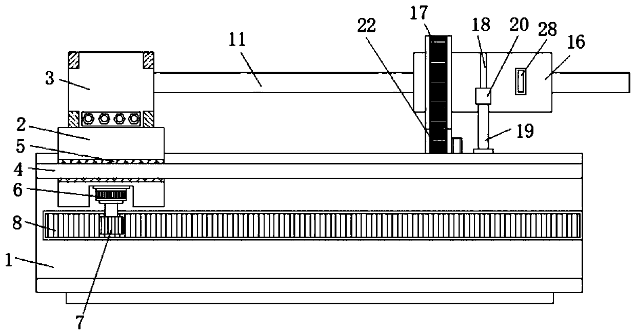
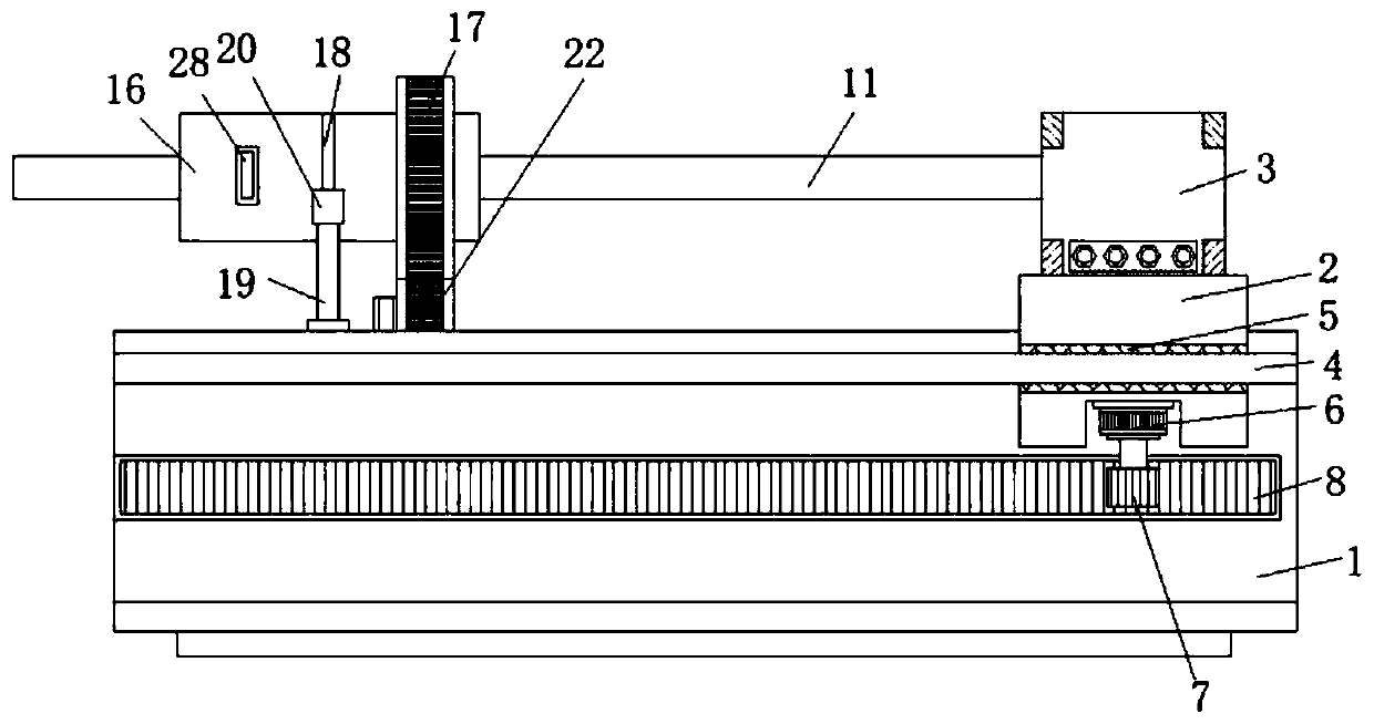
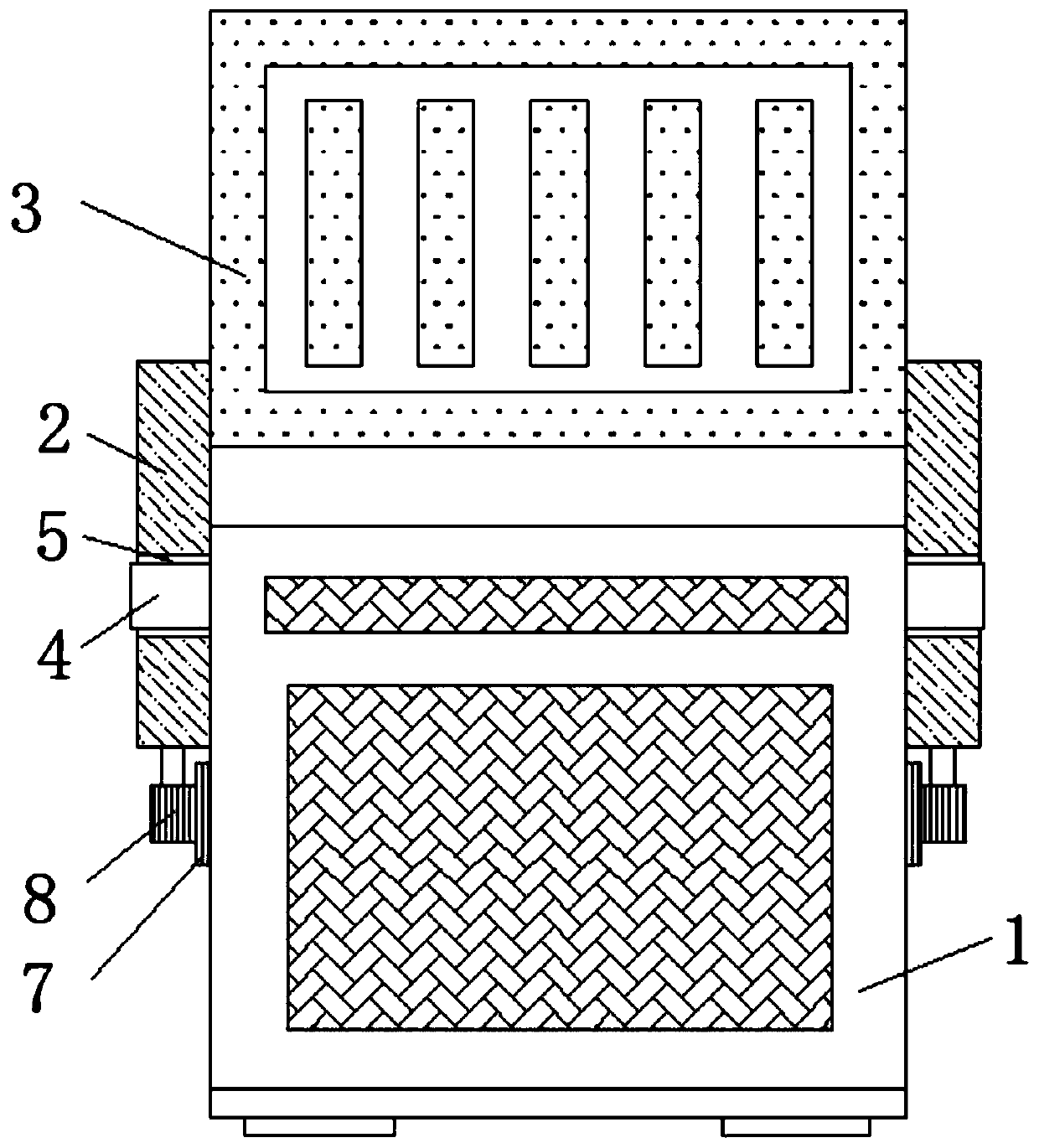
[0033] refer to Figure 1-7, an automated assembly line manufacturing process for coated copper pipes includes a processing table 1, a sliding plate 2 is horizontally slidably connected to both sides of the processing table 1, and a driving assembly is fixedly installed on the bottom of the sliding plate 2, and the two sliding plates 2 are close to each other The same fixed seat 3 is fixedly installed on one side of the fixed seat 3, and a movable clamping assembly is arranged in the fixed seat 3. The same copper pipe 11 is clamped on the movable clamping assembly, and the top of the processing table 1 is rotated and installed with a rotating sleeve 16. The outer fixed sleeve of the rotating sleeve 16 is provided with a first rotating gear 17, and the top of the processing table 1 is provided with a first groove 21, and the bottom inner wall of the first groove 21 is rotatably connected with a second rotating gear 22, and the first The rotating gear 17 is meshed with the secon...

Embodiment 2

[0035] Further improvement on the basis of the first embodiment: both sides of the processing table 1 are fixedly installed with limiting rods 4, and the sliding plate 2 is provided with limiting holes 5, and the two limiting rods 4 respectively pass through the two limiting holes 5 And it is slidingly connected with the limit hole 5, and the limit rod 4 and the limit hole 5 can be used to keep the sliding plate 2 stable when it moves laterally, so that it can move along a straight line; Drive motor 6, drive gear 7 is fixedly installed on the output shaft of drive motor 6, rack 8 is fixedly installed on both sides of processing table 1, and two drive gears 7 are meshed with two racks 8 respectively, when needed When driving the sliding plate 2 to move longitudinally, start the driving motor 6 at this time, and the driving motor 6 can drive the driving gear 7 to rotate. Under the meshing effect of the driving gear 7 and the rack 8, the sliding plate 2 can be driven to move later...


PUM


Abstract

The invention belongs to the technical field of copper pipe processing, and particularly provides an automated assembly line manufacturing technology of a coated copper pipe. The following scheme is proposed: equipment for implementing the technology comprises a processing table, wherein slide plates are in transverse sliding connection with two sides of the processing table, a driving assembly isfixedly mounted at the bottom of each slide plate, the same fixed seat is fixedly mounted on the sides, close to each other, of the two slide plates, a movable clamping assembly is arranged in the fixed seat, the same copper pipe is clamped on the movable clamping assembly, a rotating sleeve is rotationally mounted at the top of the processing table, a first rotating gear is fixedly arranged on the outer side of the rotating sleeve in a sleeving manner, a first groove is formed in the top of the processing table, and a second rotating gear is rotationally connected onto the inner wall of thebottom of the first groove. When the copper pipe is produced, the outer side of the copper pipe can be polished by automatic mechanical equipment, efficiency is increased compared with that of manualpolishing, meanwhile, the cost is reduced, and the technology has broad market promotion prospects.

Description

technical field [0001] The invention relates to the technical field of copper tube processing, in particular to an automatic assembly line manufacturing process for coated copper tubes. Background technique [0002] Copper tubes are also called copper tubes. A type of non-ferrous metal pipe, which is a pressed and drawn seamless pipe. Copper pipe has good electrical conductivity and thermal conductivity, and is the main material of conductive accessories and heat dissipation accessories of electronic products, and has become the first choice for modern contractors to install tap water pipes, heating and cooling pipes in all residential commercial buildings. Copper tubes have strong corrosion resistance, are not easy to oxidize, and are not easy to chemically react with some liquid substances, and are easy to bend. [0003] After the current coated copper pipe is molded with raw materials, the outside of the steel pipe needs to be manually polished, and it takes a long time...

Claims


Application Information

Patent Timeline
IPC IPC(8): B24B5/04B24B27/00B24B41/06B24B47/12B24B47/20B24B47/22
CPCB24B5/04B24B27/0076B24B41/067B24B47/12B24B47/20B24B47/22
Inventor 周武洋周冰周忠宝
Owner 芜湖达锦新材料科技有限公司
Why Eureka
Try Eureka