Magnetic material tray switch and implementation method thereof

A technology of magnetic materials and switches, applied in the direction of conveyors, conveyor objects, conveyor control devices, etc., can solve problems such as rising defect rate, easy scratches of paint, and many labors

Pending Publication Date: 2020-07-24
HENGDIAN GRP DMEGC MAGNETICS CO LTD
View PDF0 Cites 2 Cited by
  • Summary
  • Abstract
  • Description
  • Claims
  • Application Information

AI Technical Summary

Problems solved by technology

This station requires more labor
Moreover, due to manual operation, the paint on the first surface of the product is easy to scratch, and manual opera

Method used


Image

  • Magnetic material tray switch and implementation method thereof
  • Magnetic material tray switch and implementation method thereof
  • Magnetic material tray switch and implementation method thereof

Examples


Embodiment 1

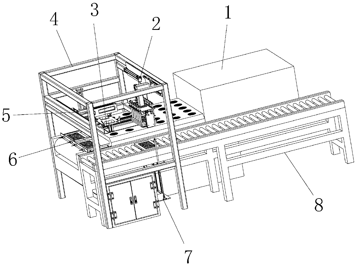
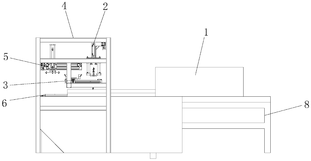
[0045] see Figure 1-10 , the present invention provides the following technical solutions: a magnetic material tray exchange, including a dryer 1 and a conveying line 8 arranged on one side of the dryer 1, an installation frame 4 is arranged above the discharge end of the dryer 1, A tray guide mechanism 6 is connected above the discharge end of the dryer 1, a first transport mechanism 5 is connected above the corresponding tray guide mechanism 6 on the installation frame 4, and a side of the first transport mechanism 5 is connected to the installation frame 4 There is a first transplanting mechanism 3, and the second transporting mechanism 2 is connected to the side where the first transplanting mechanism 3 is away from the first transporting mechanism 5 on the installation frame 4, and the second transporting mechanism 2 is connected on the conveying line 8. Corresponding to the second transplanting mechanism 7, the conveying line 8 is connected with a conveying line tray in...

Embodiment 2

[0058] The difference between this embodiment and Embodiment 1 is that further, the second transplanting mechanism 7 includes a second transplanting mechanism mounting plate 71, a second transplanting cylinder 72, a buffer 73, a tray lifting rod 74, a third Slider slide rail 75 and slide rail mounting plate 76, wherein, the second transplanting mechanism mounting plate 71 is installed on the support of conveying line 8, is connected with the 3rd slide of four symmetrical arrangements on the second transplanting mechanism mounting plate 71. Block slide rail 75, the slide block of the 3rd slide block slide rail 75 is connected on the second transplanting mechanism mounting plate 71, and the lower end of the 3rd slide block slide rail 75 slide rail is connected with slide rail mounting plate 76, is positioned at same side The upper ends of the slide rails of the two third slide block slide rails 75 are connected with the tray lifting rod 74, and the second transplanting mechanism ...


PUM


Abstract

The invention discloses a magnetic material tray switch. The magnetic material tray switch comprises a dryer and a conveying line arranged on one side of the dryer, wherein a mounting machine frame isarranged above the discharging end of the dryer, a tray guiding mechanism is connected with the upper portion of the discharging end of the dryer, a first carrying mechanism, corresponding to the upper portion of the tray guiding mechanism is connected with the mounting machine frame, a first transplanting mechanism, located on one side of the first carrying mechanism is connected with the mounting machine frame, and a second carrying mechanism, located on one side, away from one side of the first carrying mechanism of the first transplanting mechanism is connected with the mounting machine frame. The invention further discloses an implementation method of the magnetic material tray switch. According to the magnetic material tray switch, manpower can be completely replaced, a product canbe overturned completely, the automation degree is high, the working efficiency of the product overturning is greatly improved, and the labor intensity of workers is reduced. The magnetic material tray switch can completely eradicate the operation of manual overturning and tray-arranging operation on the product, and greatly improves the yield of the product.

Description

technical field [0001] The invention belongs to the technical field of magnetic material production and manufacturing, and in particular relates to a magnetic material pallet switch and a realization method thereof. Background technique [0002] Various processes of producing magnetic materials, such as pressing, sintering, grinding, checking and grading, etc., all need to load the products into pallets for handling, printing and other operations. Printing requires both sides of the product to be printed, and after printing one side, the paint must be dried first, and then turned over for printing on the other side. The current flipping work is to manually take the product out of the tray, turn it over and put it into another tray, and then enter the next printing process after the other tray is full. This station requires more labor. Moreover, due to manual operation, the paint on the first surface of the product is easy to scratch, and manual operation is also prone to p...

Claims


Application Information

Patent Timeline
IPC IPC(8): B65G47/91B65G47/248B65G43/08B65G47/88
CPCB65G43/08B65G47/248B65G47/88B65G47/914B65G2201/0258B65G2203/0233
Inventor 牛利博袁美华厉力波沈厉齐玉昌方秀平
Owner HENGDIAN GRP DMEGC MAGNETICS CO LTD
Why Eureka
Try Eureka