
Coke oven ascension pipe evaporator connecting structure and manufacturing method thereof

A technology of connection structure and production method, which is applied in the direction of coke oven, flange connection, heating of coke oven, etc., can solve the problems of damage, low sewage discharge efficiency, complicated sewage operation, etc., and achieves reduction in the number of sewage valves and easy sewage operation. , Reasonable effect of connection structure design

Pending Publication Date: 2020-07-24
MAANSHAN IRON & STEEL CO LTD
View PDF0 Cites 0 Cited by
  • Summary
  • Abstract
  • Description
  • Claims
  • Application Information

AI Technical Summary

Problems solved by technology

[0003] During the use of this technology, there are the following disadvantages: 1. When the gas outlet temperature of the rising tube evaporator at the end of coking is less than 400 °C, the inner wall of the evaporator is easy to absorb tar and graphite; More than 100 blowdown valves are opened and closed, and the operation is cumbersome, resulting in heavy blowdown work and low blowdown efficiency
The connection structure of the existing coke oven riser tube evaporator is as follows: image 3 As shown, the original sewage valve 10 has many settings, and the sewage discharge operation is cumbersome
[0004] The above-mentioned deficiencies will easily cause local medium retention or impurity precipitation and scaling in the riser tube evaporator, which will reduce the local heat transfer performance of the inner wall of the riser tube evaporator and cause problems such as overheating, deformation, damage, and leakage.

Method used


Image

  • Coke oven ascension pipe evaporator connecting structure and manufacturing method thereof
  • Coke oven ascension pipe evaporator connecting structure and manufacturing method thereof
  • Coke oven ascension pipe evaporator connecting structure and manufacturing method thereof

Examples


Embodiment Construction

[0027] The specific implementation manner of the present invention will be described in further detail below by describing the embodiments with reference to the accompanying drawings.

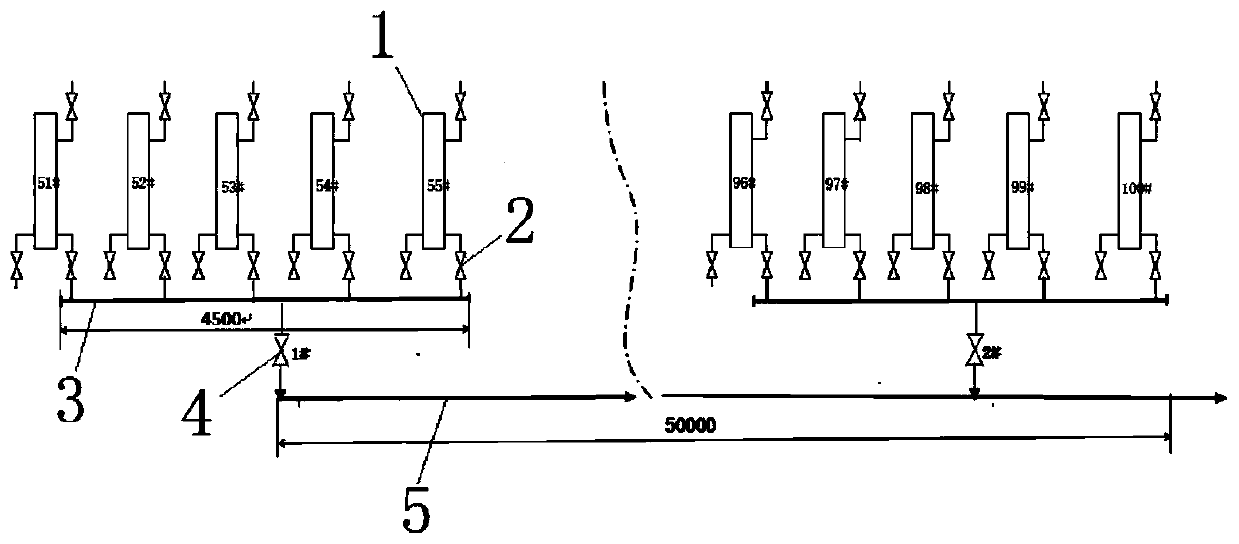
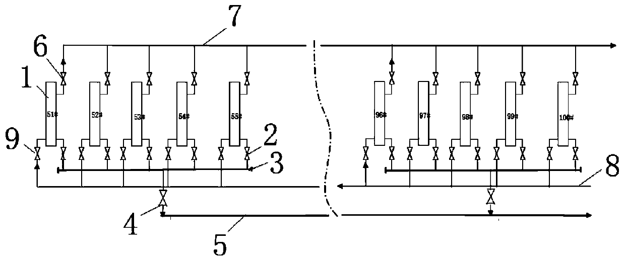
[0028] Such as figure 1 and figure 2 As shown, the connection structure of the coke oven riser evaporator includes a sewage discharge pipe 5, a blowdown valve 4, a group of riser evaporators 1 arranged side by side, a group of balance valves 2 and a communication pipe 3; several adjacent riser evaporators The riser evaporator 1 forms a riser evaporator interconnection unit, and all the riser evaporators in each riser evaporator interconnection unit are connected to the same communication pipe 3 through the corresponding balance valve 2, forming a group of riser evaporators arranged side by side. The interconnection unit of the evaporator; the communication pipes corresponding to the interconnection units of different riser pipe evaporators are connected to the sewage pipe 5 through the corre...


PUM


Abstract

The invention discloses a coke oven ascending pipe evaporator connecting structure and a manufacturing method thereof. The connecting structure comprises blow-off water pipes, blow-off valves and a group of ascending pipe evaporators which are arranged side by side, and the connecting structure further comprises a set of balance valves and a communicating pipe. The plurality of adjacent ascendingpipe evaporators form an ascending pipe evaporator interconnection unit; all the ascending pipe evaporators in each ascending pipe evaporator interconnection unit are connected with the same communicating pipe through the corresponding balance valves, and the communicating pipes corresponding to the different ascending pipe evaporator interconnection units are connected with the blow-off water pipes through the corresponding blow-off valves. Through normally open communication of the balance valves, media in the multiple ascending pipe evaporators in the same group are subjected to mutual convection and automatically exchange heat, so that the temperature of the inner walls of the ascending pipe evaporators in the final coking stage of a carbonization chamber is increased, and the problemthat tar and graphite are easily adsorbed on the inner walls of the evaporators in the final coking stage is solved; and the quantity of the blow-down valves is greatly reduced, and the blow-down operation is simple and convenient.

Description

technical field [0001] The invention relates to the technical field of coke ovens, in particular to a coke oven rising tube evaporator connection structure and a manufacturing method thereof. Background technique [0002] Utilization of waste heat from raw coke oven gas is a new technology for the coking industry to develop circular economy and save energy. In the process of popularization and application, the internal wall accumulation of tar, graphite and internal leakage in the riser evaporator are the key factors restricting the popularization of this technology. Since the temperature difference of the raw gas output from the coke oven carbonization chamber is as high as 350°C during each turnaround time, the temperature of the raw gas output from the carbonization chamber at the end of the coking stage drops significantly, below 400°C, and the inner wall of the riser is easy to absorb tar and graphite. [0003] During the use of this technology, there are the following ...

Claims


Application Information

Patent Timeline
IPC IPC(8): C10B27/00C10B43/00C10B43/14F16L23/026
CPCC10B27/00C10B43/00C10B43/14F16L23/026
Inventor 李平夏鹏飞钱虎林邓海龙蒋玄甘恢玉戴干邵峰戴波徐刚
Owner MAANSHAN IRON & STEEL CO LTD
Learn More