Cooling fin, heating unit and electric radiator

A technology of heat sink and heating body, which is applied in the directions of space heating and ventilation, space heating and ventilation details, household heating, etc. The effect of reducing thermal conductivity and preventing burns to users

Pending Publication Date: 2020-07-24
GREE ELECTRIC APPLIANCES INC
View PDF0 Cites 0 Cited by
  • Summary
  • Abstract
  • Description
  • Claims
  • Application Information

AI Technical Summary

Problems solved by technology

[0004] Therefore, the technical problem to be solved by the present invention is to overcome the defects in the prior art that increase the heat dissipation surface area of ​​the electric heating oil to prevent the surface temperature of the electric heating oil from being too high, resulting in an increase in the occupied area and mass of the electric heating oil, thereby providing a heat dissipation Sheet and heating element and electric heater

Method used


Image

  • Cooling fin, heating unit and electric radiator
  • Cooling fin, heating unit and electric radiator
  • Cooling fin, heating unit and electric radiator

Examples


Embodiment 1

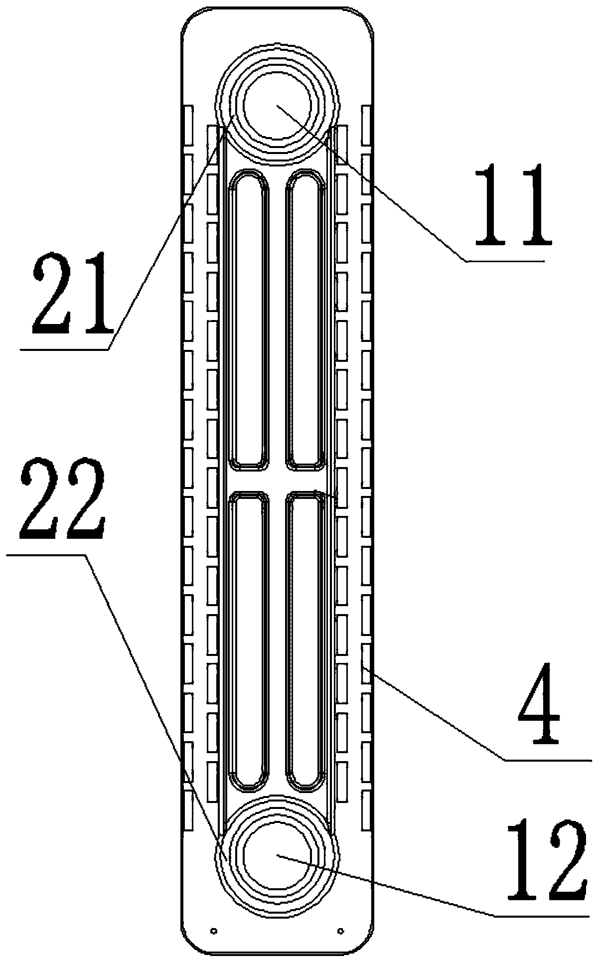
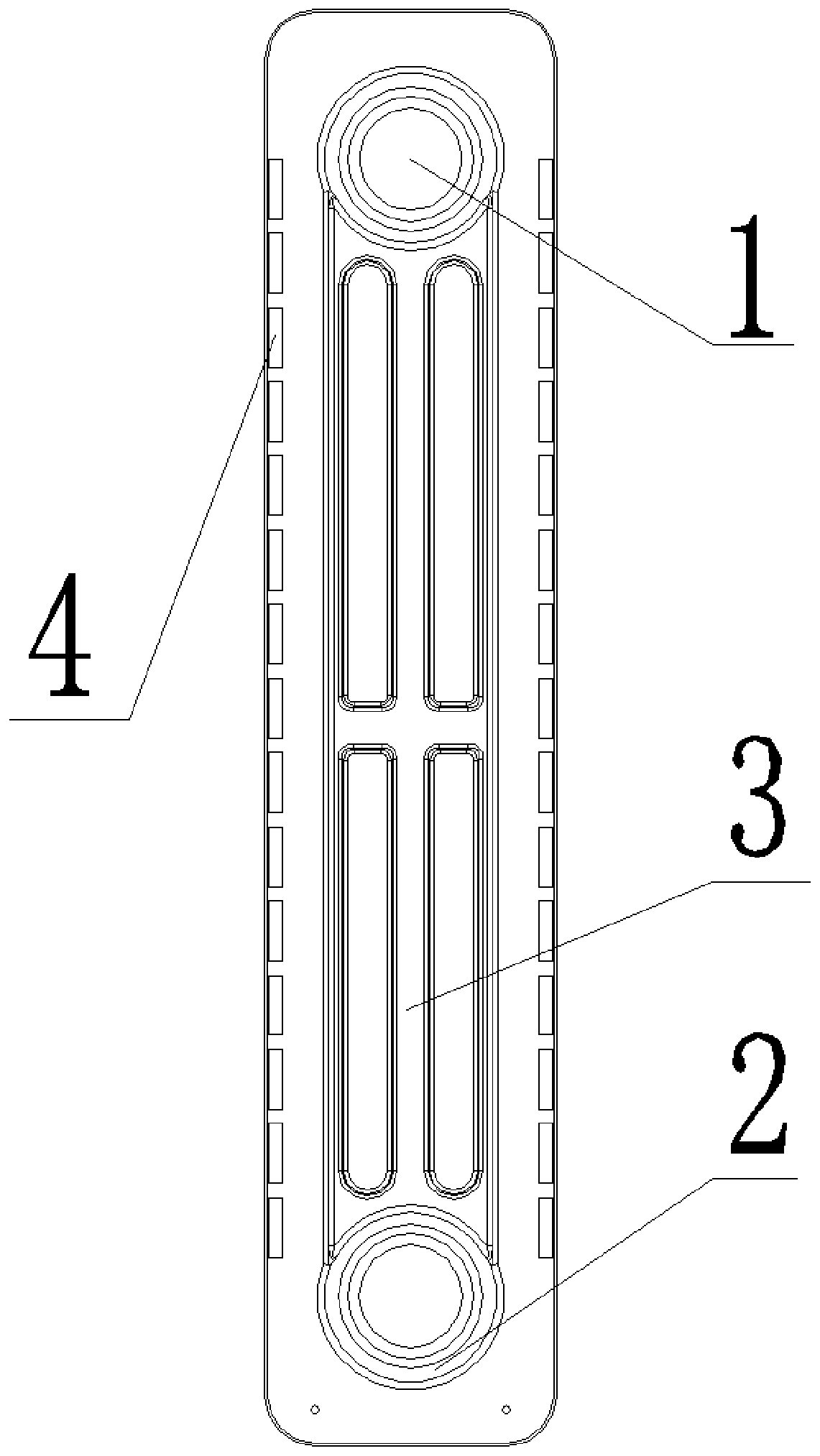
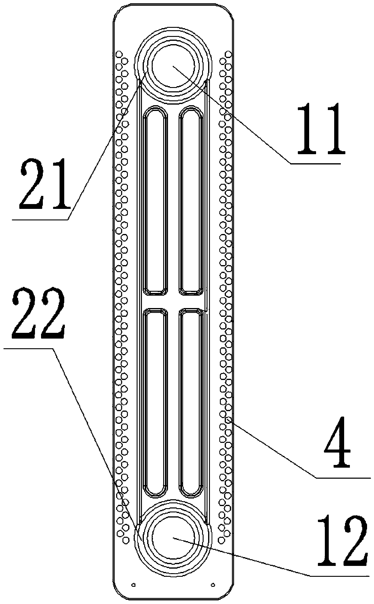
[0039] Such as figure 1 - Figure 4 As shown, the present embodiment provides a heat sink, which includes a heat conduction oil passage 32 , a heat conduction oil passage and a through hole 4 .

[0040] The heat sink is in the shape of a rectangular sheet, each corner is rounded, and includes a cavity 1. The cavity 1 is respectively provided with an upper cavity part 11 and a lower cavity part 12 along the height direction. The lower cavity part 12 is connected with the heating rod. The upper oil bag 21 is arranged on the side of the cavity 11, and the lower oil bag 22 is arranged along the side of the lower cavity 12. And heat-conducting oil is arranged in the heat-conducting oil circuit.

[0041] In this embodiment, the heat conduction oil passages are three-way, arranged along the vertical direction, and the middle parts of the three heat conduction oil passages are connected. As an alternative embodiment, the heat conduction oil passage can be arranged in a curved cross...

Embodiment 2

[0049] This embodiment provides a heating element, including the heat sink and the heating rod provided in Embodiment 1. Several above-mentioned cooling fins are arranged side by side with each other, and the heating rod is penetrated at the position of the hole-shaped lower cavity 12 of each cooling fin at the same time, for heating the lower oil bag 22 .

Embodiment 3

[0051] This embodiment provides an electric heater, including the heating element, temperature control element, indicator light, auxiliary device and other structures provided in Embodiment 2. Both the temperature control element and the indicator light are arranged on the heating body, and the indicator light is electrically connected with the temperature control element.

[0052] The auxiliary device includes but is not limited to: a clothes hanger, which is arranged above the heating element, and is suitable for drying clothes, etc.; it can also be a mobile bracket, which is arranged at the bottom of the heating element, and is used to support the heating element or drive the heating element. body to move. The mobile bracket itself can be a folding structure or an integrally formed structure. When the folding structure is adopted, it is convenient to reduce the space occupation when it is idle and improve the storage efficiency of the electric heater.

[0053] The electric...


PUM


Abstract

The invention provides a cooling fin, a heating unit and an electric radiator. The cooling fin comprises an oil pocket structure and a heat conduction oil path. The oil pocket structure comprises an upper oil packet formed on the top of the cooling fin and a lower oil packet formed on the bottom of the cooling fin. The heat conduction oil path communicates with the upper oil packet and the lower oil packet, and the area between the heat conduction oil path and the edge of the adjacent cooling fin is provided with through holes. The oil pocket structure is heated through a heating rod, heat conduction oil in the oil packets is subjected to convective circulation along the oil path, and heat is radiated out through the cooling fin. The through holes are formed between the edge of the coolingfin and the heat conduction oil path, which can change the heat conductivity coefficient of the center high-temperature area of the oil path to the edge of the cooling fin, so that a part of temperature transmission mediums are turned into air from metal, and thus the heat conductivity is lowered, the purpose of heat insulation is achieved, the temperature of the edge of the cooling fin is lowered, and the cooling fin is prevented from scalding a user. By forming the through holes, the problem can be solved that in the prior art, since the superficial area of heat dissipation of the outer contour of an electric heating oil heater is increased, the occupation area and weight of the oil heater are increased.

Description

technical field [0001] The invention relates to the technical field of household appliances, in particular to a heat sink, a heating element and an electric heater. Background technique [0002] Electric oil heater is a safe and reliable space heater popular in recent years. This kind of heater usually installs the heating rod inside the cavity of the heat sink, and injects heat-conducting oil into the oil circuit around the cavity. When the power is turned on, the heat conduction oil around the heating rod is heated, rises to the upper part of the cavity, circulates convectively along the oil circuit, and radiates heat out through the surface of the heat sink, thereby heating the space environment. The air-cooled heat transfer oil descends along the oil path to around the heating rod and is heated again to start a new cycle. [0003] According to the current national standard, there are regulations on the temperature rise limit of the heater surface to prevent the risk of ...

Claims


Application Information

Patent Timeline
Patent Type & Authority Applications(China)
IPC IPC(8): F24D19/00F24D13/04F24D19/10
CPCF24D13/04F24D19/00F24D19/1096F24D2200/08F24D2220/2036
Inventor 何应明左双全林康桂李姗璇李航斌
Owner GREE ELECTRIC APPLIANCES INC
Why Eureka
Try Eureka