Eureka AIR delivers breakthrough ideas for toughest innovation challenges, trusted by R&D personnel around the world.

Drill and knife grinding device

A tool sharpening device and drill grinding technology, which is applied in the direction of grinding drive devices, grinding machines, drilling tool accessories, etc., can solve the problems of poor drill bit and tool effect, high cost and complexity, etc.

Inactive Publication Date: 2020-07-28
黄良华
View PDF4 Cites 0 Cited by
  • Summary
  • Abstract
  • Description
  • Claims
  • Application Information

AI Technical Summary

Problems solved by technology

[0003] The object of the present invention is to provide a kind of drill grinding and knife sharpening device to solve the problem of high cost and complexity of drill bits and knife sharpeners in the market, low cost and simple and difficult to use grinding drill bits and cutter effects no problem

Method used


Image

  • Drill and knife grinding device
  • Drill and knife grinding device
  • Drill and knife grinding device

Examples


Embodiment 1

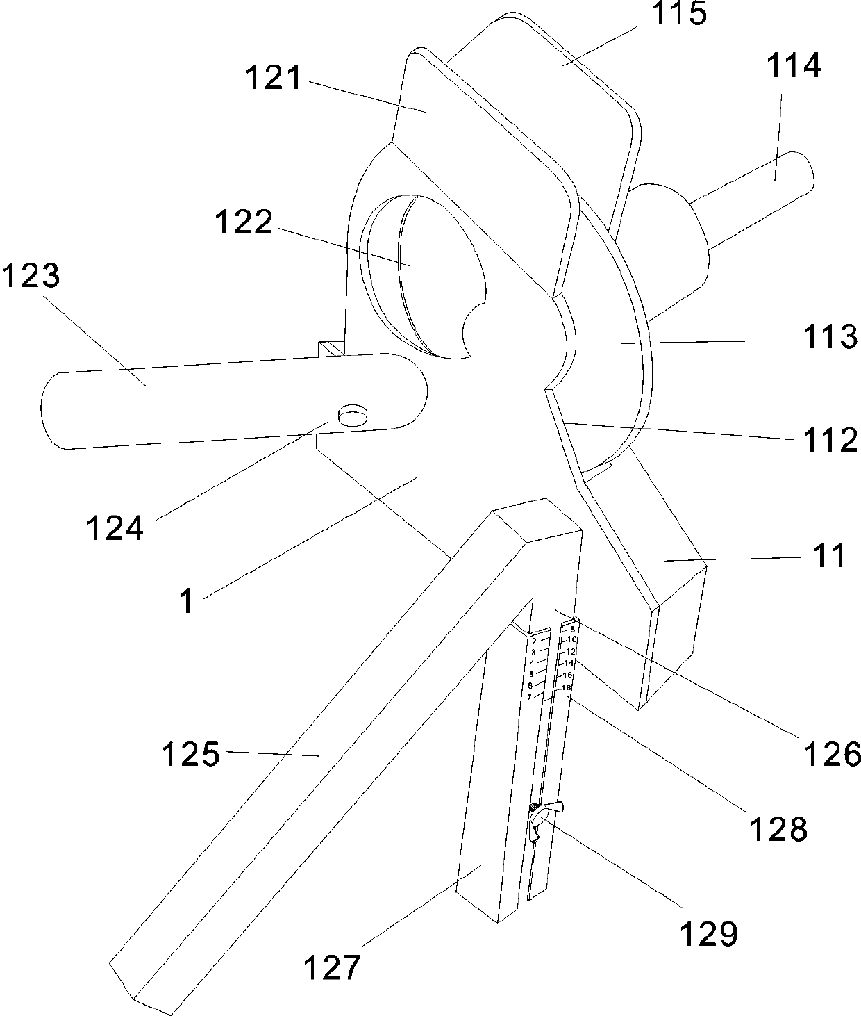
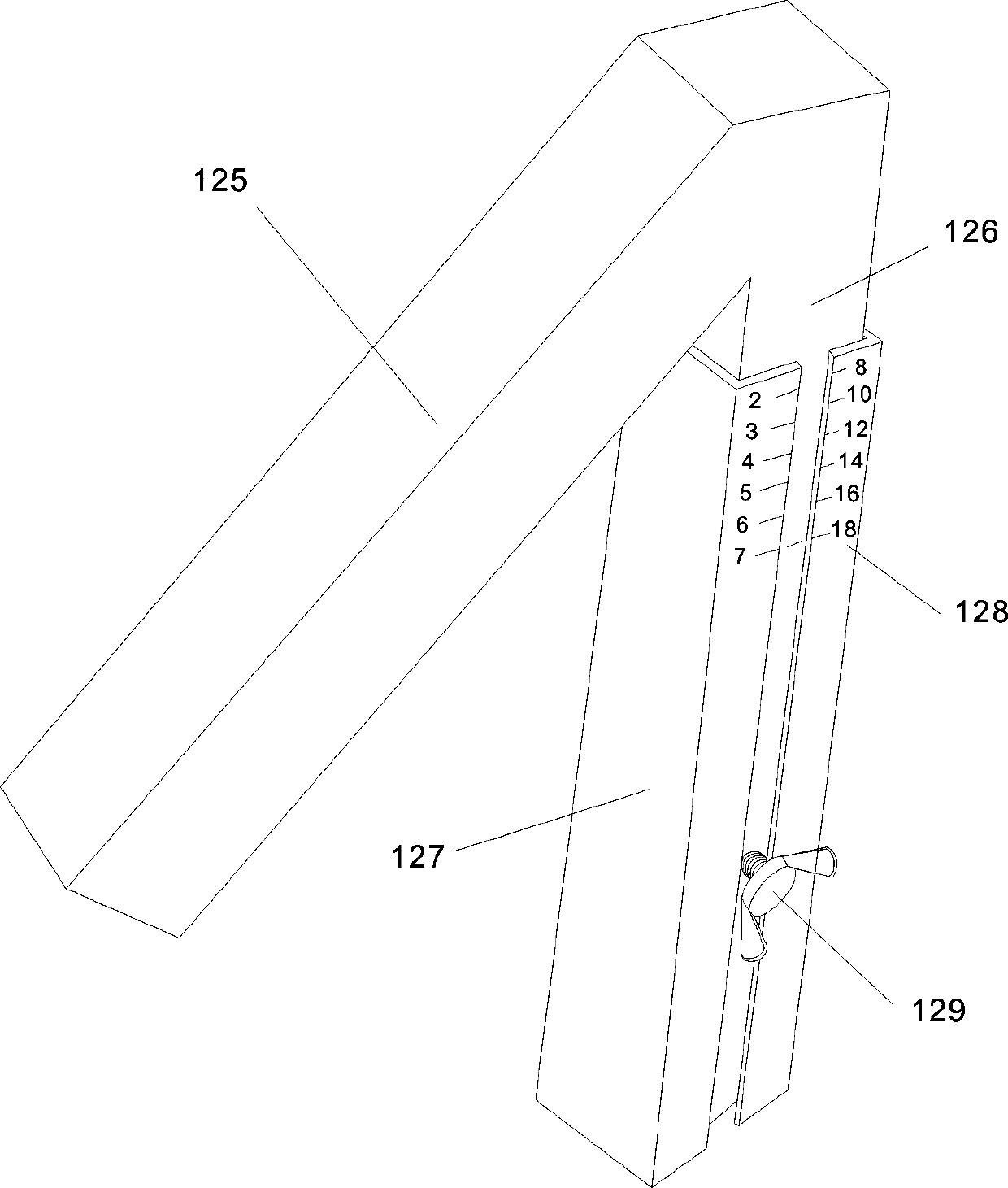
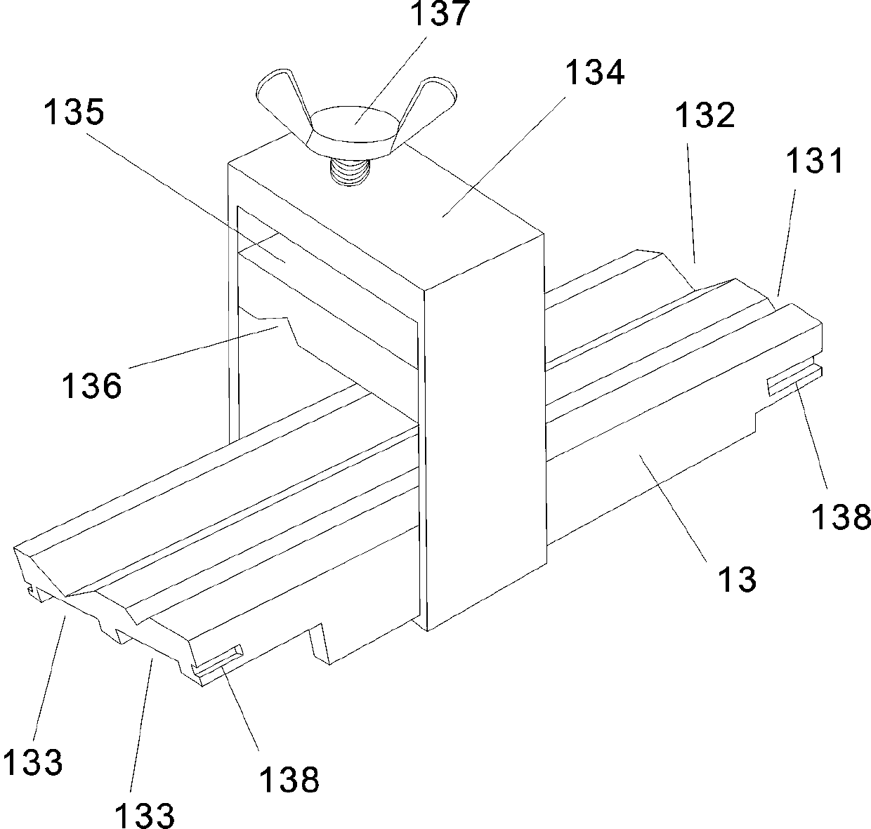
[0014] A kind of drill and knife sharpening device The drill and knife sharpening device 1, the angle grinding sleeve rod 123, the inner angle grinding sleeve rod 125, the outer cover 112, the drill bit sleeve 13, the clamping block 134, the inner angle grinding lifting tube 127 , the top of angle block 14, motor transmission rod 114, emery wheel 113, outer cover 112 is provided with right sharpening bevel 121, and the left upper left of support 11 is provided with left sharpening bevel 115, and the left side of outer cover 112 is also provided with Hole 122.

[0015] The upper left side of the machine base 11 is provided with a left sharpening bevel 115 and a grinding wheel 113 to form a V-shaped opening. When the knife is sharpened, it can be pulled through and sharpened. There is an opening in the middle with bearings on both sides for the insertion of the motor transmission rod 114. 1. One end of the motor transmission rod 114 is equipped with a grinding wheel 113, and one...

Embodiment 2

[0019] The double grinding wheel device 2, the double grinding wheel base 22, the angle grinding sleeve rod 123, the inner angle grinding sleeve rod 125, the outer cover 112, the drill bit sleeve 13, the clamping block 134, the inner angle grinding device Lifting pipe 127, opposite angle block 14, motor transmission rod 114, back cover 225, left gear 223, right gear 224, left emery wheel 223, right emery wheel 224, the top of described outer cover 112 is provided with right grinder bevel 121, The upper left of the double grinder base 22 is provided with a left sharpening bevel 115 .

[0020] The left grinding wheel 223 is set on the upper left of the double grinding wheel base 22, and the right grinding wheel 224 is arranged on the upper right to form a counter-grinding drill angle 244. The inner angle lifting pipe 127 of the grinding wheel is arranged in the middle of the double grinding wheel base 22, and the angle grinding cover rod 123 is connected thereto. Said double gri...


PUM


Abstract

The invention relates to the technical field of drill and knife grinding devices, in particular to a drill and knife grinding device. The drill and knife grinding device is characterized by includinga double grinding wheel device, a machine base, an angle grinding sleeve rod, an inner angle grinding sleeve rod, an outer cover, a placing drill sleeve, a clamping block, an inner angle grinding lifting tube, an angle align block, a motor drive rod, a grinding wheel, a double grinding wheel base, a back cover, a left gear, a right gear, a left grinding wheel and a right grinding wheel. A right knife grinding inclined edge is arranged on the upper edge of the outer cover, a left knife grinding inclined edge is arranged on the upper left side of the machine base, an opening is formed in the left edge of the outer cover, the cost is low, the efficiency is high, and the effect is good.

Description

technical field [0001] The invention relates to the technical field of drill and knife sharpening devices, in particular to a drill and knife sharpening device. Background technique [0002] With the progress of society and the demand of the market, people have higher and higher requirements for drill and knife sharpeners. They must be easy to use, simple and low in price. At present, the cost and price of drill and knife sharpeners on the market are high. And complex, low cost and simple, it is not easy to use the drill bits and cutters that are ground out, and the effect is not good. Contents of the invention [0003] The purpose of the present invention is to provide a kind of drill grinding and knife sharpening device, to solve the effect of high cost and complicated, low cost and simple and difficult to use grinding drill bits and knife sharpeners on the market. No problem waiting. [0004] In order to achieve the above object, the present invention adopts such tech...

Claims


Application Information

Patent Timeline
Patent Type & Authority Applications(China)
IPC IPC(8): B24B3/00B24B3/24B24B27/00B24B47/12B24B49/02
CPCB24B3/24B24B3/00B24B3/247B24B27/0076B24B47/12B24B49/02
Inventor 黄良华
Owner 黄良华
Why Eureka
Eureka Blog
Learn More