System and method for monitoring mechanical components inside a wind turbine nacelle

A technology of mechanical parts and monitoring system, applied in the field of monitoring, can solve the problems of consuming a lot of human and material resources, high fan maintenance cost, increasing fan inspection and maintenance cost, etc., so as to improve the fan inspection and maintenance efficiency and reduce maintenance. cost and the effect of fault location

Active Publication Date: 2022-01-21
SHANGHAI ELECTRIC WIND POWER GRP CO LTD
View PDF0 Cites 0 Cited by
  • Summary
  • Abstract
  • Description
  • Claims
  • Application Information

AI Technical Summary

Problems solved by technology

[0002] For fan failures caused by mechanical component failures inside the fan nacelle, such as yaw bearings and yaw gears inside the fan nacelle, such as stuck teeth, broken teeth, etc., there is generally no special installation in the fan nacelle for monitoring machinery. Component equipment often requires manual maintenance to locate faults and then repair faults, which consumes a lot of human and material resources, and the maintenance cost of fans is relatively high.
In addition, fans are usually installed in remote places, which further increases the cost of fan inspection and maintenance

Method used


Image

  • System and method for monitoring mechanical components inside a wind turbine nacelle
  • System and method for monitoring mechanical components inside a wind turbine nacelle
  • System and method for monitoring mechanical components inside a wind turbine nacelle

Examples


Embodiment 1

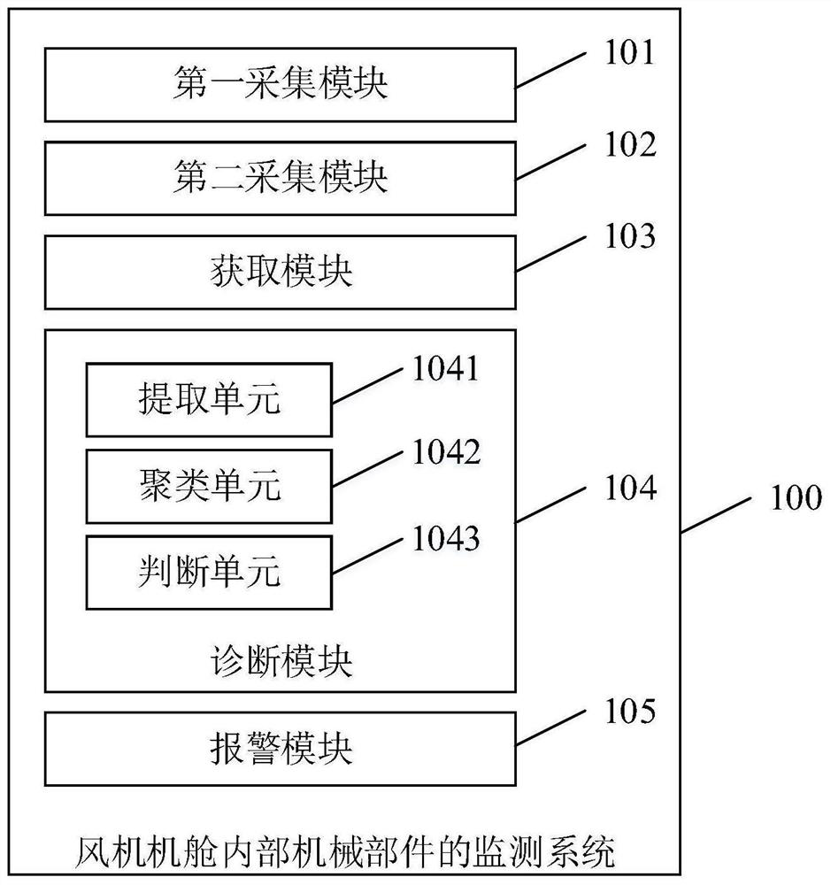
[0051] This embodiment provides a monitoring system for mechanical components inside the fan nacelle, figure 1 A schematic diagram of the modules of this embodiment is shown. refer to figure 1 , the monitoring system of the present embodiment includes:

[0052] The first collection module 101 is configured to collect a first audio signal at mechanical components inside the fan nacelle.

[0053] In this embodiment, the mechanical components may be mechanical components such as bearings, gears, etc. that need to be monitored in real time in the yaw system and pitch system inside the fan nacelle. Since the operation of the mechanical components will generate audio signals, the Therefore, the normal operation of the mechanical component can be shown as generating a stable audio signal, so it can be judged and analyzed whether the mechanical component fails based on the collected first audio signal of the mechanical component.

[0054] Specifically, in this embodiment, the first...

Embodiment 2

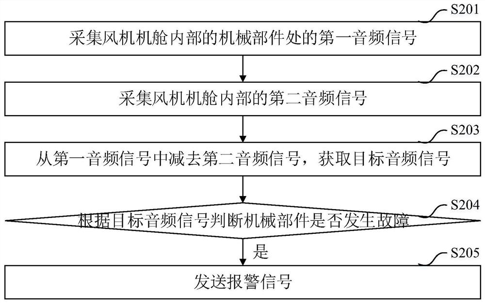
[0091] This embodiment provides a method for monitoring the mechanical components inside the fan nacelle, image 3 A flowchart of this embodiment is shown. refer to image 3 , the monitoring method of the present embodiment includes:

[0092] S201. Collect a first audio signal at a mechanical component inside a fan nacelle.

[0093] In this embodiment, the mechanical components may be mechanical components such as bearings, gears, etc. that need to be monitored in real time in the yaw system and pitch system inside the fan nacelle. Since the operation of the mechanical components will generate audio signals, the Therefore, the normal operation of the mechanical component can be shown as generating a stable audio signal, so it can be judged and analyzed whether the mechanical component fails based on the collected first audio signal of the mechanical component.

[0094] Specifically, in this embodiment, a directional acquisition module such as a directional microphone array ...


PUM


Abstract

The invention discloses a monitoring system and method for mechanical components inside a fan machine room. Wherein, the monitoring system includes: a first acquisition module, arranged inside the fan cabin, for collecting the first audio signal at the mechanical parts inside the fan cabin; a second acquisition module, arranged inside the fan cabin, for Collecting a second audio signal inside the fan cabin; an acquisition module, configured to subtract the second audio signal from the first audio signal to obtain a target audio signal; a diagnostic module, configured to judge the target audio signal based on the target audio signal Check if any mechanical parts mentioned above are malfunctioning. The invention realizes the internal fault monitoring and positioning of the fan cabin without personally visiting the fan site, reduces the maintenance cost and improves the maintenance efficiency.

Description

technical field [0001] The invention relates to the technical field of monitoring, in particular to a monitoring system and method for mechanical components inside a fan nacelle. Background technique [0002] For fan failures caused by mechanical component failures inside the fan nacelle, such as yaw bearings and yaw gears inside the fan nacelle, such as stuck teeth, broken teeth, etc., there is generally no special installation in the fan nacelle for monitoring machinery. Component equipment often requires manual maintenance to locate faults and then repair faults, which consumes a lot of human and material resources, and the maintenance cost of fans is relatively high. In addition, the wind turbines are usually installed in remote places, which further increases the cost of inspection and maintenance of the wind turbines. Contents of the invention [0003] The technical problem to be solved by the present invention is to provide a monitoring system and method for the me...

Claims


Application Information

Patent Timeline
Patent Type & Authority Patents(China)
IPC IPC(8): F03D17/00
CPCF03D17/00Y02E10/72
Inventor 司伟蒋勇许移庆
Owner SHANGHAI ELECTRIC WIND POWER GRP CO LTD
Why Eureka
Try Eureka