Method for testing transverse bending resistance of small hinge joint hollow slab bridge combined reinforcing member

A technology of reinforcement member and test method, which is applied in the direction of using stable bending force to test material strength, using stable tension/pressure test material strength, measuring device, etc., can solve the problem of insignificant reinforcement effect and easy damage of small hinged joint , weak structure and other problems, to achieve the effect of simple and fast test method and strong operability

Active Publication Date: 2020-07-28
TAIZHOU UNIV +1
View PDF7 Cites 2 Cited by
  • Summary
  • Abstract
  • Description
  • Claims
  • Application Information

AI Technical Summary

Problems solved by technology

[0002] Hollow slabs with small hinges rely on the structure of small hinges to form a whole. Small hinges are easily damaged, causing the single plate to be stressed, resulting in damage to the bridge structure. At present, the bridge deck pavement is replaced, carbon fiber or steel plate is pasted to address the stress of the single plate. In other methods, there is a large increase in dead load, and it takes a long time to interrupt the traffic during operation. Lateral prestressing technology is also used, but because the hinge gap is difficult to deal with, it affects the reinforcement effect. The reinforcement technology in the prior art either only strengthens the lateral connection. Either only enhance the bearing capacity of a single girder, and the reinforcement effect is not obvious. Due to the weak hinge structure of the prefabricated small hinged hollow slab bridge, the hinged joints are prone to damage under the action of heavy vehicles, causing longitudinal cracking of the bridge deck pavement, which seriously damages the beam. The slab is in a single-slab stress state, resulting in damage to the bridge structure
[0003] Chinese invention patent CN103174098B discloses a reinforcement method for reinforced concrete to deal with single-slab stress, including the following steps: a. According to the length and structure of the single-span bridge, press it into U-shaped steel with flange, and the steel flange is provided with through holes; b. . Roughen the surface concrete on the base plates on both sides of the hinged joint of the hollow plate, and drill holes on the base plate according to the hole position of the U-shaped steel flange of the flange; c. Clean the drilled holes and implant anchor screws in the through holes; d. Anchor and install the flange U-shaped steel on the hollow slab; pour concrete through the hinged joints of the hollow slab. It can improve the lateral distribution of load and the bearing capacity of single girder, and solve the problem of small hinge joint hollow slab veneer stress reinforcement, but the transverse bending performance of the reinforced bridge hinged hollow slab girder is difficult to judge, so a transverse bending resistance is needed. Bending performance test method to judge transverse bending performance

Method used


Image

  • Method for testing transverse bending resistance of small hinge joint hollow slab bridge combined reinforcing member
  • Method for testing transverse bending resistance of small hinge joint hollow slab bridge combined reinforcing member
  • Method for testing transverse bending resistance of small hinge joint hollow slab bridge combined reinforcing member

Examples


Embodiment 1

[0032] Such as Figure 1 to Figure 9 As shown, the test method for transverse flexural performance of composite reinforced members of small hinged hollow slab bridges includes the following steps:

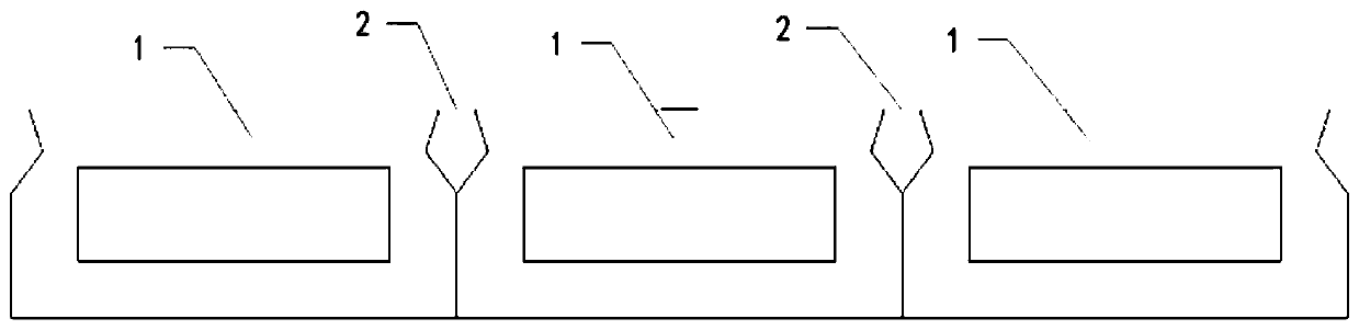
[0033] Step 1, such as figure 1 As shown, three small hinged hollow slab specimens 1 of the same length are cut from the same small hinged hollow slab bridge member, and the three small hinged hollow slab specimens 1 are placed side by side to form two hinged joints 2;

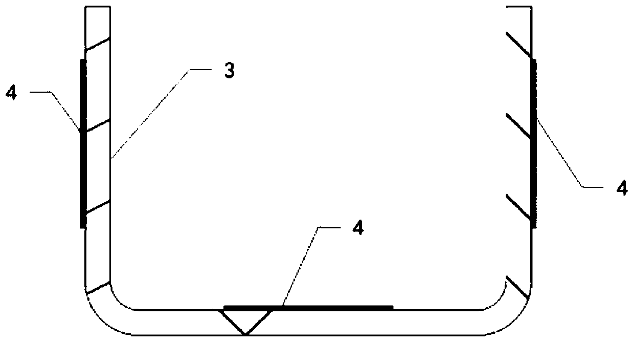
[0034] Step two, such as figure 2 As shown, the U-shaped shear reinforcement 3 is prepared, and at least three resistance strain gauges 4 are arranged on the U-shaped shear reinforcement 3, and the resistance strain gauges 4 are respectively arranged on the outside of the vertical reinforcement of the U-shaped shear reinforcement 3. side and upper sides of transverse reinforcement;

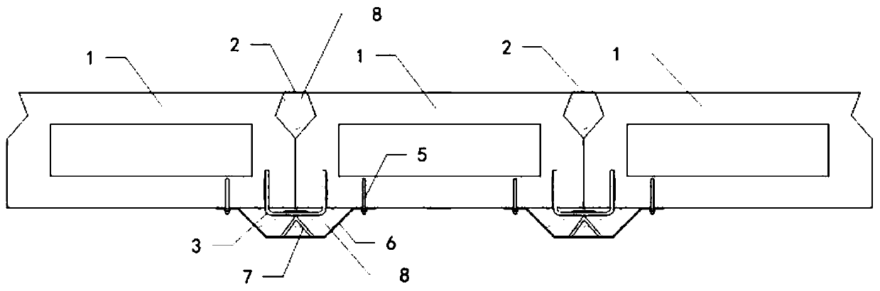
[0035] Step three, such as image 3 As shown, the U-shaped shear reinforcement 3 is implanted at the bottom position below the h...

Embodiment 2

[0044] Such as Figure 1 to Figure 9 As shown, the test method for transverse flexural performance of composite reinforced members of small hinged hollow slab bridges includes the following steps:

[0045] Step 1, such as figure 1 As shown, three small hinged hollow slab specimens 1 of the same length are cut from the same small hinged hollow slab bridge member, and the three small hinged hollow slab specimens 1 are placed side by side to form two hinged joints 2;

[0046] Step two, such as figure 2 As shown, the U-shaped shear reinforcement 3 is prepared, and at least three resistance strain gauges 4 are arranged on the U-shaped shear reinforcement 3, and the resistance strain gauges 4 are respectively arranged on the outside of the vertical reinforcement of the U-shaped shear reinforcement 3. side and upper sides of transverse reinforcement;

[0047] Step three, such as image 3 As shown, the U-shaped shear reinforcement 3 is implanted at the bottom position below the h...


PUM

PropertyMeasurementUnit
lengthaaaaaaaaaa

Abstract

The invention discloses a method for testing the transverse bending resistance of a small hinge joint hollow slab bridge combined reinforcing member and relates to the technical field of bridge reinforcement. The method comprises sample piece manufacturing and testing. According to the method of the invention, the small hinge joint hollow slab bridge combined reinforcing member is subjected to miniaturization processing, so that the goal of accurately testing the member in a laboratory is achieved; in a testing process, a static strain acquisition system is adopted to record the strain conditions of U-shaped shear reinforcements, flanged trapezoidal steel plates and concrete, meanwhile, record the displacement of the midspan and fulcrum of a test member, so that the various transverse bending resistance performance parameters of the small hinge joint hollow slab bridge combined reinforcing member are obtained. The test method is simple, convenient, rapid and high in operability.

Description

technical field [0001] The invention relates to the technical field of bridge reinforcement, in particular to a method for testing the transverse bending resistance of a small-hinged hollow slab bridge composite reinforcement component. Background technique [0002] Hollow slabs with small hinges rely on the structure of small hinges to form a whole. Small hinges are easily damaged, causing the single plate to be stressed, resulting in damage to the bridge structure. At present, the bridge deck pavement is replaced, carbon fiber or steel plate is pasted to address the stress of the single plate. In other methods, there is a large increase in dead load, and it takes a long time to interrupt the traffic during operation. Lateral prestressing technology is also used, but because the hinge gap is difficult to deal with, it affects the reinforcement effect. The reinforcement technology in the prior art either only strengthens the lateral connection. Either only enhance the bearin...

Claims


Application Information

Patent Timeline
Patent Type & Authority Applications(China)
IPC IPC(8): G01N3/08G01N3/20G01N3/06
CPCG01N3/08G01N3/20G01N3/062G01N3/066G01N2203/0003G01N2203/0019G01N2203/0023G01N2203/0605G01N2203/0623G01N2203/0682G01N2203/0676
Inventor 金辉卢光沈一军蒋金跃程嘉稀姜凤华邵国涛吕国平张利
Owner TAIZHOU UNIV
Why Eureka
Try Eureka