
Corrosion resistance tester for coated metal material

A metal material, corrosion resistance technology, applied in the field of corrosion resistance test equipment, can solve the problems of difficult to optimize the coating conditions, difficult to easily evaluate the coated steel plate, etc., to achieve the effect of improving the adhesion

Active Publication Date: 2020-07-28
MAZDA MOTOR CORP
View PDF10 Cites 0 Cited by
  • Summary
  • Abstract
  • Description
  • Claims
  • Application Information

AI Technical Summary

Problems solved by technology

[0003] However, in such a corrosion promotion test, it takes several months to perform the evaluation, so for example, it is difficult to easily evaluate the constituent materials of the coated steel sheet or the quality of the coating film with different baking conditions, and it is difficult to quickly optimize the coating conditions, etc.

Method used


Image

  • Corrosion resistance tester for coated metal material
  • Corrosion resistance tester for coated metal material
  • Corrosion resistance tester for coated metal material

Examples


no. 1 approach

[0066]

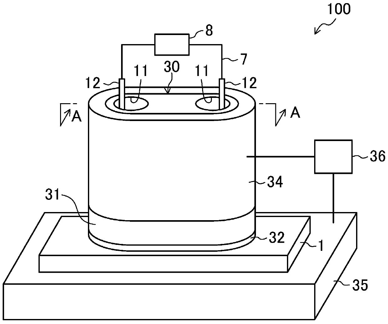
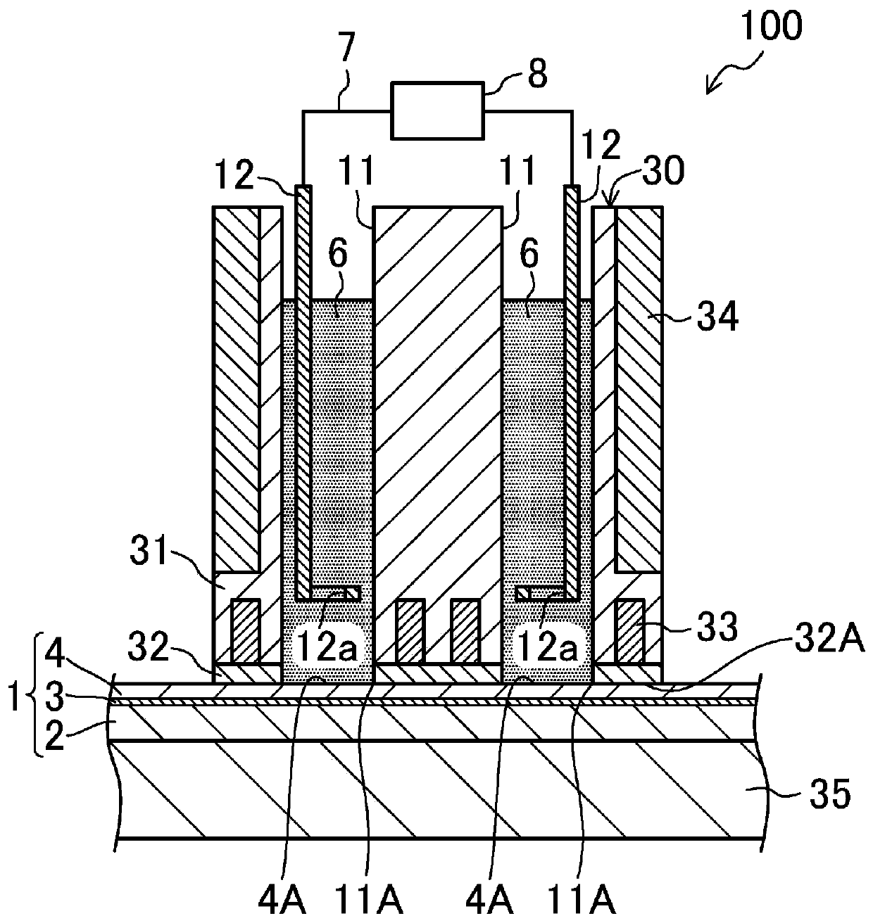
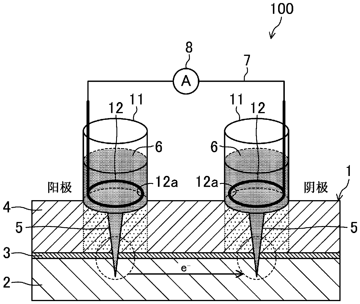
[0067] Such as Figure 1 ~ Figure 3 As shown, the corrosion resistance test device 100 according to this embodiment is a device for testing the corrosion resistance of the clad metal material 1, and includes a container 30, an aqueous electrolyte material 6, an electrode 12, an external circuit 7, and a power supply unit 8 , a rubber heater 34 (first heating element), a heating plate 35 (second heating element), and a temperature controller 36 .

[0068]

[0069] Such as figure 2 , image 3 As shown, the specific conditions of the clad metal material 1 are as follows: a chemical conversion film 3 is formed on the surface of the steel plate 2, and the steel plate 2 and the chemical conversion film 3 are both metal substrates, and are formed on the steel plate 2 on which the chemical conversion film 3 has been formed. There is a resin coating film as a surface treatment film, that is, the electrophoretic coating film 4 in this embodiment.

[0070] Such as figu...

no. 2 approach

[0155] Next, other embodiments related to the present invention will be described in detail. It should be noted that, in the description of these embodiments, the same parts as those of the first embodiment are denoted by the same reference numerals, and detailed description thereof will be omitted.

[0156] You can also set Figure 13 cover 38 shown to cover the figure 1 The container 30 and the cladding metal material 1. The cover 38 includes, for example, a cover main body 381 , a notch portion 382 provided on a side surface of the cover main body 381 , and a grip portion 383 provided on an upper portion of the cover main body 381 . Hold the grip portion 383 , take out the wires of the external circuit 7 and the temperature controller 36 from the notch portion 382 , and arrange the cover 38 so that the entire container 30 and clad metal material 1 are covered with the cover main body 381 . According to this structure, it is easy to adjust the temperature of the aqueous e...


PUM

PropertyMeasurementUnit
thicknessaaaaaaaaaa
diameteraaaaaaaaaa

Abstract

The invention discloses a corrosion resistance tester for a coated metal material. The coated metal material is obtained by forming a surface treatment film on a metal substrate. The orrosion resistance tester includes: a container placed on the surface treatment film and including a plurality of water-containing electrolyte material holders that open through the bottom surface in contact with thesurface treatment film; the water-containing electrolyte material contained in each of the water-containing electrolyte material holders of the container, and being in contact with an associated oneof a plurality of separate measurement target portions of the surface treatment film; a plurality of electrodes being each in contact with the water-containing electrolyte material contained in an associated one of the water-containing electrolyte material holders; an external circuit connecting the electrodes together; and a conduction means configured to conduct electricity to the metal substrate through the electrodes and the external circuit.

Description

technical field [0001] The present disclosure relates to a corrosion resistance test device for a coated metal material. Background technique [0002] So far, as a method of evaluating the performance of the coating film, corrosion acceleration tests such as combined cycle test and salt spray test are carried out. [0003] However, in such a corrosion promotion test, several months are required for evaluation, so for example, it is difficult to easily evaluate the constituent materials of the coated steel sheet or the quality of the coating film with different baking conditions, and it is difficult to quickly optimize the coating conditions, etc. . Therefore, it is desired to establish a quantitative evaluation method for quickly and easily evaluating the corrosion resistance of coated steel sheets in the fields of material development, process management of coating plants, and quality control related to vehicle rust prevention. [0004] On the other hand, as a method of e...

Claims


Application Information

Patent Timeline
Patent Type & Authority Applications(China)
IPC IPC(8): G01N17/02
CPCG01N17/006G01N17/02G01N17/00G01N17/04C23F13/04C23F13/02C23F2213/32
Inventor 浅田照朗佐佐木将展重永勉
Owner MAZDA MOTOR CORP
Learn More