Composite material curing deformation simulation modeling method based on fiber placement track

A technology of curing deformation and simulation modeling, applied in design optimization/simulation, constraint-based CAD, instruments, etc., to achieve a wide range of applications

Active Publication Date: 2020-07-28
CHENGDU AIRCRAFT INDUSTRY GROUP
View PDF3 Cites 11 Cited by
  • Summary
  • Abstract
  • Description
  • Claims
  • Application Information

AI Technical Summary

Problems solved by technology

However, this method is suitable for three-dimensional solid geometric flat plates, ...

Method used


Image

  • Composite material curing deformation simulation modeling method based on fiber placement track
  • Composite material curing deformation simulation modeling method based on fiber placement track

Examples


Embodiment 1

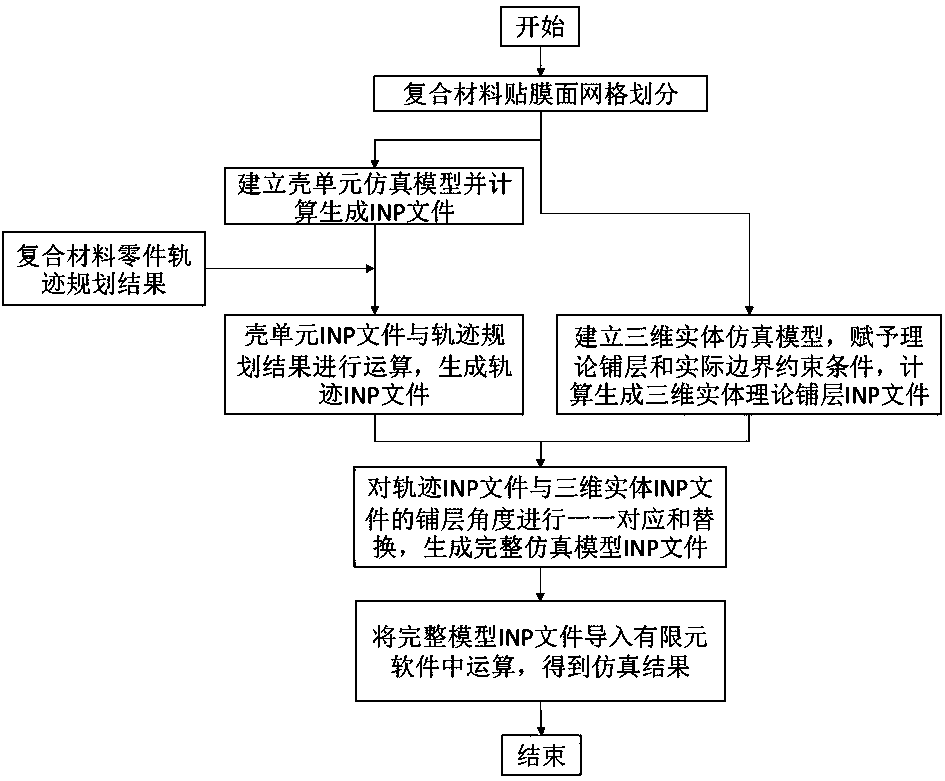
[0029] A simulation modeling method for solidification deformation of composite materials based on wire laying trajectory, such as figure 1 As shown, it mainly includes the following steps:

[0030] Step S1: In the finite element software, perform finite element mesh division on the film surface of the composite material part manufactured by the automatic wire laying equipment to form a shell element mesh model;

[0031] Step S2: Carry out simulation calculation on the shell element mesh model, and generate an INP file of the shell element mesh model including mesh node information;

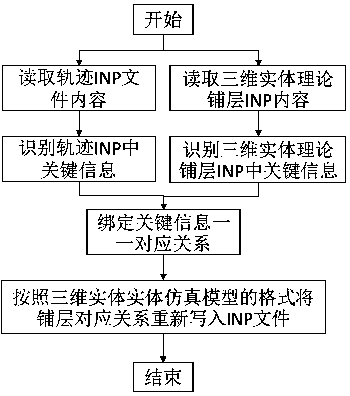
[0032] Step S3: Import the INP file of the mesh model of the shell element into the automatic wire laying trajectory planning and design software, and perform calculations together with the results of the automatic wire laying trajectory planning of the composite material part to generate a fiber laying including grid nodes and fiber laying trajectory planning Trajectory INP file with angle info...

Embodiment 2

[0038] This embodiment is optimized on the basis of Embodiment 1. The shell element mesh model in the step S2 and the 3D solid theory layup INP file in the step S4 are generated based on the same mesh model. The INP file in the step S2 is a type of file generated by the finite element software, and the INP file records the model data and historical data of the finite element model, such as node coordinates, elements, material properties, and the like.

[0039] The automatic wire laying trajectory planning and design software described in step S3 is a necessary design software for the manufacture of composite material parts by using automatic wire laying equipment, which can realize the planning of wire laying trajectory according to the structural characteristics of composite material parts, and form the The result of the automatic laying trajectory planning of the composite material part. It should be noted that the geometric model used for trajectory planning of composite pa...

Embodiment 3

[0046] A simulation modeling method for solidification deformation of composite materials based on wire laying trajectory, such as figure 1 As shown, it mainly includes the following steps:

[0047] Step S1: In the finite element software Abaqus, perform finite element mesh division on the film surface of the composite material part manufactured by the automatic wire laying equipment;

[0048] In this embodiment, the finite element mesh division and analysis of the composite material parts is carried out by using the finite element analysis software Abaqus, and the film surface of the composite material part is imported into the Abaqus analysis software, and the film surface is meshed. Grid type and grid size are not required. In this embodiment, in order to facilitate subsequent operations and data processing and application, quadrilateral structured, type S4R grids are used for division, and after the grid division of all models is completed, the create mesh function is use...


PUM


Abstract

The invention discloses a composite material solidification deformation simulation modeling method based on a fiber placement track, and the method comprises the steps: meshing a film pasting surfaceof a composite material part into a shell unit grid model, and generating an INP file through simulation operation; performing operation on the INP file of the shell element grid model and an automatic fiber placement trajectory planning result to generate a trajectory INP file; establishing a complete composite material simulation model, and generating a three-dimensional entity theoretical layupINP file; replacing the actual angle in the track INP file with the theoretical angle in the three-dimensional entity theoretical layup INP file to form a complete simulation model INP file; and calculating the complete INP file to obtain a deformation simulation result. When curing deformation simulation analysis is carried out on a composite material part manufactured by adopting an automatic fiber placement technology, modeling can be carried out on the basis of a real track of fiber placement, and the curing deformation condition of a composite material part can be analyzed more truly andaccurately.

Description

technical field [0001] The invention belongs to the technical field of solidification deformation simulation of composite materials, and in particular relates to a simulation modeling method for solidification deformation of composite materials based on wire laying track. Background technique [0002] Composite material solidification deformation simulation technology is one of the effective methods to solve the quality problem of solidification deformation of composite material parts after molding and demoulding. It is mainly based on the geometric structure, material type and boundary constraints of composite material parts for simulation modeling and calculation. Analyze and take further compensation measures to control the degree of deformation or counteract the effect of deformation. [0003] At present, in the process of simulation modeling of composite materials, the modeling is mainly based on the part tooling surface and the theoretical lay-up angle given by the des...

Claims


Application Information

Patent Timeline
IPC IPC(8): G06F30/23G06F113/26G06F111/04
Inventor 邹尧聂海平蔡豫晋陈浩然谢林杉
Owner CHENGDU AIRCRAFT INDUSTRY GROUP
Why Eureka
Try Eureka