Mechanical Mechanism and Working Method of Pipe Grinding Robot

A mechanical mechanism and robot technology, applied in the field of robotics, can solve problems such as insufficient grinding, insufficient grinding, casualties, etc.

Active Publication Date: 2021-07-06
ZHONGBEI UNIV
View PDF11 Cites 1 Cited by
  • Summary
  • Abstract
  • Description
  • Claims
  • Application Information

AI Technical Summary

Problems solved by technology

Fatigue, noise, vibration and dust will all cause harm to the body of workers, and when grinding pressure pipes, once an accident occurs, it is very easy to cause casualties
Moreover, some pipes are close to the wall, so manual polishing is inconvenient, and it is prone to disadvantages such as insufficient polishing or even insufficient polishing.
[0004] At present, the use of more mature polishing and grinding machines cannot polish the non-detachable pipes installed on the job site
In addition, there are currently some reports or patents on the research of walking robots outside the pipe, but most of these robots are used for pipe quality inspection, and their mechanical structure characteristics are not suitable for pipe grinding.
There are few reports or patents on grinding robots specially used for grinding non-removable pipelines on construction sites.

Method used


Image

  • Mechanical Mechanism and Working Method of Pipe Grinding Robot
  • Mechanical Mechanism and Working Method of Pipe Grinding Robot
  • Mechanical Mechanism and Working Method of Pipe Grinding Robot

Examples


Embodiment Construction

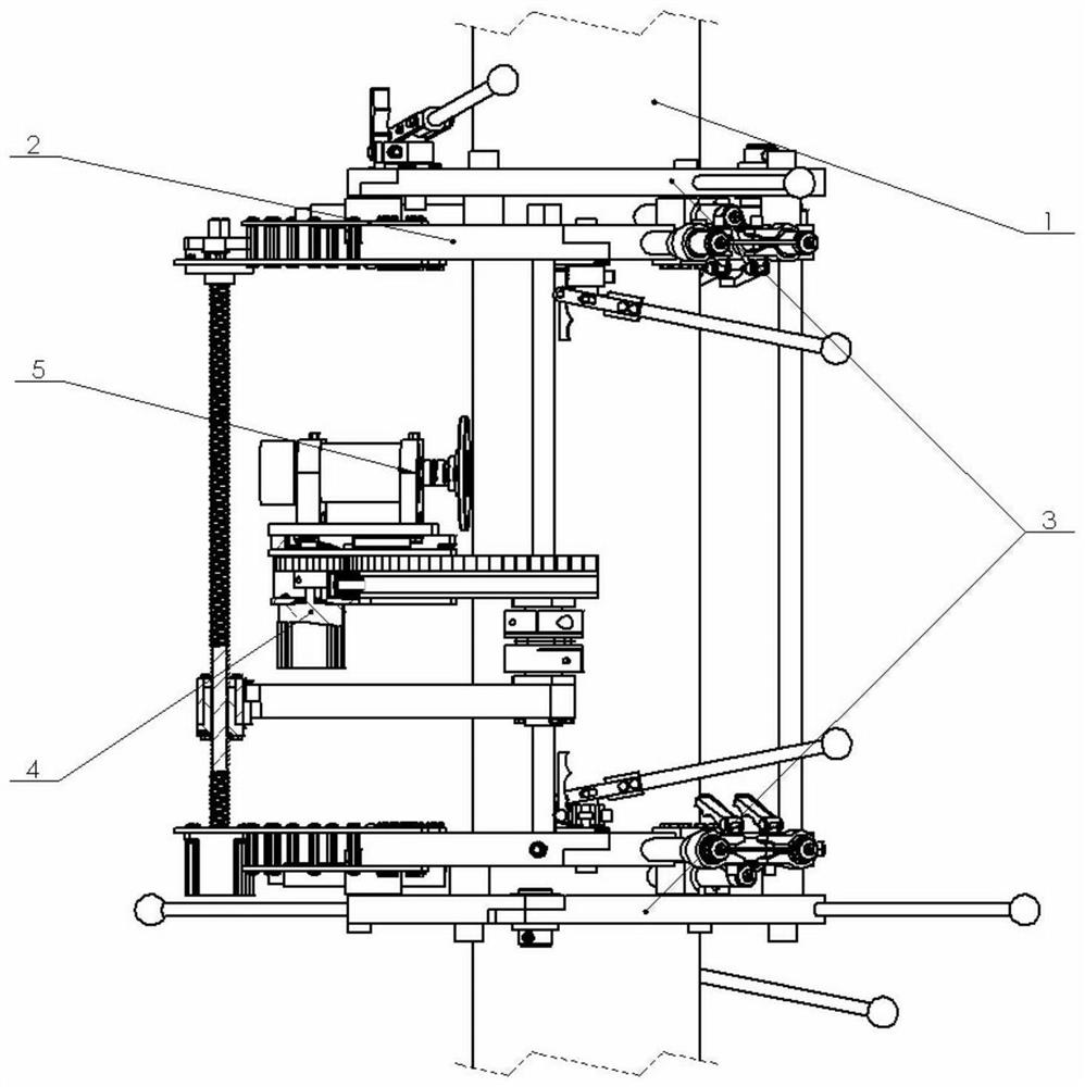
[0039] Combine below figure 1 The mechanical mechanism of the present invention will be described.

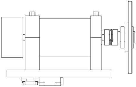
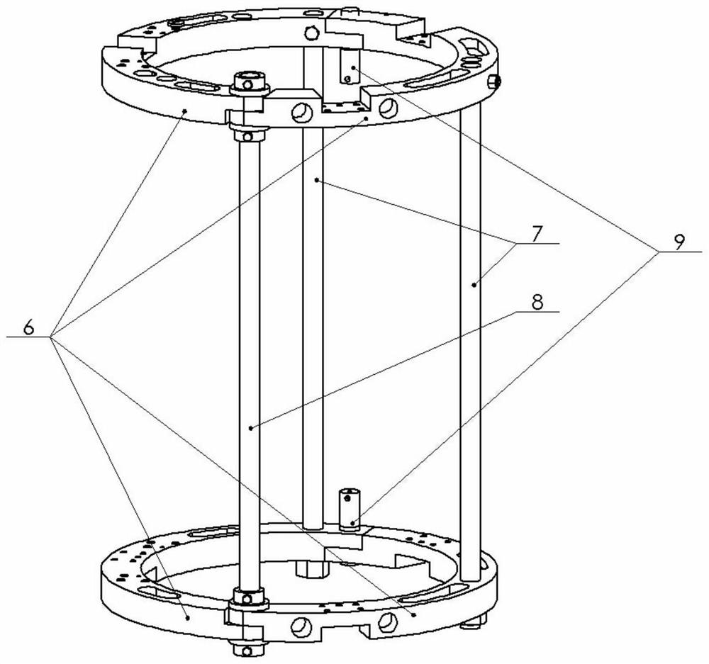
[0040] Such as figure 1 As shown, the mechanical mechanism of the present invention is mainly composed of a frame component 2 , a pipe clamping device 3 , a motion system 4 and a grinding assembly 5 . The frame part 2 is the basis of the whole mechanical mechanism. After the robot is installed, the frame part 2 is in a closed ring shape and surrounds the pipeline 1 to be polished. There are two pipe clamping devices 3 which are respectively fixed on the upper and lower ends of the frame part 2 to play the role of fixing the robot on the pipeline 1 to be polished. Driven by each motor, the motion system 4 drives the grinding assembly 5 to move outside the pipeline to be polished 1 through the cooperation of the lead screw 13 and the gear train, and the movement has three dimensions, which are respectively moving back and forth along the axis of the pipeline, and moving around ...


PUM


Abstract

The invention discloses a mechanical structure of a pipeline grinding robot, which is used for grinding pipelines. The mechanical structure includes frame parts, pipe clamping device, motion system, and grinding assembly; the motion system drives the grinding assembly to move freely along three dimensions, namely, moving back and forth along the axis of the pipeline, moving circularly around the axis of the pipeline to be polished, and moving toward the The grinding pipeline moves back and forth in the radial direction, and the high-speed rotating motor assembled on the grinding assembly drives the grinding wheel, which can fully polish the area to be polished of the pipeline to be polished. The invention also discloses the working method of the mechanical structure. The motion system can move freely in three dimensions along the pipeline axis direction, the circumferential direction of the pipeline to be polished, and the radial direction of the pipeline to be polished. The grinding component is installed on the motion system, driven by the motion system Next, the grinding assembly can move freely along the above three dimensions, and the area to be polished of the pipeline to be polished is polished under the action of the high-speed rotating grinding wheel on the grinding assembly. Three-dimensional grinding, good flexibility and high grinding precision.

Description

technical field [0001] The invention relates to a robot, in particular to a robot for grinding the outer surface of a pipe or a cylinder. The pipe or cylinder is installed on the work site, and the pipe does not need to be disassembled; it is mainly used in petrochemical, thermal power plants, boiler rooms, etc. Grinding work before regular inspection of disassembled or inconveniently disassembled industrial pressure pipelines. [0002] technical background [0003] According to the "Pressure Pipeline Safety and Supervision Regulations", industrial pressure pipelines must be inspected regularly. There are a large number of pressure pipes in petrochemical, thermal power plants, boilers and other places. There are more than 270 thermal power plants affiliated to the five major power generation companies alone, and each thermal power plant has a large number of pipelines that need to be cleaned and polished every year. At present, the vast majority of pipes are manually polish...

Claims


Application Information

Patent Timeline
Patent Type & Authority Patents(China)
IPC IPC(8): B24B5/40B24B41/02B24B41/00
CPCB24B5/40B24B41/00B24B41/02
Inventor 孙虎儿张佳航邢宇峰
Owner ZHONGBEI UNIV
Why Eureka
Try Eureka