Eureka AIR delivers breakthrough ideas for toughest innovation challenges, trusted by R&D personnel around the world.

Method for mounting main bridge variable cross-section continuous steel truss girder by using cable crane

A technology of cable crane and steel truss girder, which is applied in the direction of erecting/assembling bridges, bridges, bridge forms, etc., which can solve the difficulty of horizontal and vertical transportation of components to the construction work surface, and the lack of rear balance section assembly site for bridges in mountainous areas. Problems such as the force of the large pier-beam joint are achieved to facilitate vertical and horizontal transportation, increase the construction work surface, and speed up the construction progress

Pending Publication Date: 2020-07-31
CCCC SHEC FOURTH ENG +1
View PDF11 Cites 1 Cited by
  • Summary
  • Abstract
  • Description
  • Claims
  • Application Information

AI Technical Summary

Problems solved by technology

Factors such as variable cross-section steel truss girders, long approach bridges, and their location on curves determine that traditional construction methods such as jacking are not suitable for the installation of main girders. Even if jacking methods can be used, bridges in mountainous areas do not have rear balance sections assembled At the same time, it is very difficult to set up temporary buttresses; if the bridge deck crane is used for cantilever assembly construction, the weight of the bridge deck crane will not only increase the force on the pier-beam junction, but also the components will be transported horizontally and vertically from the assembly site to the construction work surface also very difficult

Method used


Image

  • Method for mounting main bridge variable cross-section continuous steel truss girder by using cable crane
  • Method for mounting main bridge variable cross-section continuous steel truss girder by using cable crane
  • Method for mounting main bridge variable cross-section continuous steel truss girder by using cable crane

Examples


Embodiment 1

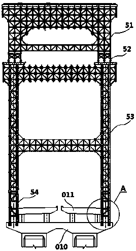
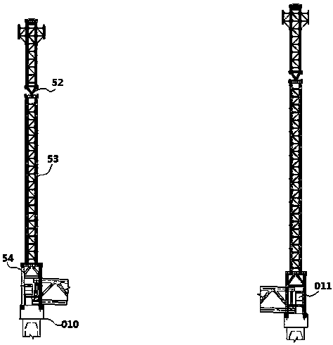
[0070] Such as figure 1 with figure 2 As shown, a cable crane in this embodiment includes a main anchor 01, a main load-bearing cable 02, a wind cable, a lifting trolley, a cable saddle and a tower, and the tower includes a left bank tower 05 and a right bank tower 07; Among them, there are two main anchors 01 on the left and right banks, and the two main anchors 01 on each bank are symmetrically arranged on both sides of the centerline of the main bridge of the bridge, and respectively correspond to the layout of the left and right bridges. The two main anchors 01 on each bank are respectively The centerline of the left and right bridges is arranged, and each main anchorage 01 is 8.5m away from the longitudinal axis of the cable crane (the centerline of the main bridge of the bridge), and the main anchorages 01 on both banks are anchored by reinforced concrete pile cap structure.

[0071] It should be noted that the bridge in this embodiment includes a curved section and a ...


PUM


Abstract

The invention discloses a method for installing a main bridge variable cross-section continuous steel truss girder by using a cable crane, and belongs to the field of bridges. The method comprises thesteps of firstly, constructing a pier top steel truss girder; then conducting main girder cantilever assembling construction, specifically, hoisting steel truss girder sections on the two sides of each main pier through symmetrical cantilevers of the cable crane, and installing the steel truss girder sections; arranging a lower parallel connection concrete plate at the steel truss girder section,and conducting construction of a second steel truss girder section of each main pier; after third steel truss girder sections of the main piers are connected, pouring concrete into the steel truss girder rod pieces of the sections; after the concrete in the rod pieces meets the requirement, conducting next steel truss girder section construction of each main pier, and stopping mid-span construction until the previous section of the closure section is reached. By adopting the scheme, the acting force of the deck crane on the steel truss girder is avoided, the stress of the pier girder joint part is reduced, the symmetrical cantilever assembly can be realized relative to each bridge main pier, the construction operation surface is increased, and the construction progress is accelerated.

Description

technical field [0001] The invention relates to the technical field of bridge construction, and more specifically relates to a method for installing a variable-section continuous steel truss girder of a main bridge by using a cable crane. Background technique [0002] Due to the large-span variable cross-section steel truss girder continuous rigid frame bridge has a large spanning capacity and a light superstructure, it is a reasonable bridge structure form for crossing deep trenches, canyons and rivers. However, due to terrain constraints, these bridges are often difficult to install with large cranes, and it is even more difficult for large transport vehicles to reach each construction work surface. [0003] The current traditional construction technology of continuous rigid frame bridges at home and abroad generally adopts the push (drag) method and the cantilever assembly method of the bridge deck crane; for long-span steel truss bridges, if the cantilever is too large ...

Claims


Application Information

Patent Timeline
IPC IPC(8): E01D21/00E01D21/10E01D6/00
CPCE01D21/00E01D21/105E01D6/00
Inventor 蔡俊华魏玉吉林金舜兰升元江超张佑义秦小晶张滔郑强吴杨史结琼
Owner CCCC SHEC FOURTH ENG
Why Eureka
Eureka Blog
Learn More