Distributed optical fiber sensing system for low-frequency detection

A distributed optical fiber, sensing system technology, applied in measurement devices, geophysical measurements, and the use of wave/particle radiation, etc., can solve the problems of high noise, affecting the low-frequency characteristics of the system, and difficult to meet the detection of low-frequency weak vibration signals.

Inactive Publication Date: 2020-07-31
INST OF SEMICONDUCTORS - CHINESE ACAD OF SCI
View PDF6 Cites 5 Cited by
  • Summary
  • Abstract
  • Description
  • Claims
  • Application Information

AI Technical Summary

Problems solved by technology

The existing distributed optical fiber sensing system based on phase-generated carrier technology also has relatively high noise in the low frequency band, mainly because optical devices such as narrow linewidth and high coherence light sources, acousto-optic modulators, and erbium-doped fiber amplifiers are affected by 1 / f Noise influence, as the frequency decreases, the noise of the device itself increases significantly. In addition, the low-frequency disturbance of the environment where the instrument is located (not the environment where the sensing fiber is located) will also affect the low-frequency characteristics of the system. Therefore, the above-mentioned distributed optical fiber sensing system is difficult. Meet the detection of low-frequency weak vibration signals

Method used


Image

  • Distributed optical fiber sensing system for low-frequency detection
  • Distributed optical fiber sensing system for low-frequency detection
  • Distributed optical fiber sensing system for low-frequency detection

Examples


Embodiment Construction

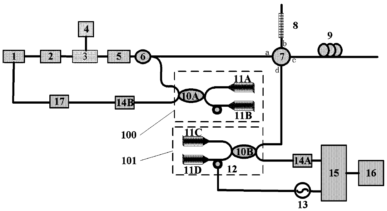
[0050] Specific embodiments of the present disclosure will be described in detail below, and it should be noted that the embodiments described here are only for illustration, and are not intended to limit the embodiments of the present disclosure. In the following description, numerous specific details are set forth in order to provide a thorough understanding of the embodiments of the present disclosure. It will be apparent, however, to one of ordinary skill in the art that these specific details need not be employed to practice the disclosed embodiments. In other instances, well-known structures, materials or methods have not been described in detail to avoid obscuring embodiments of the present disclosure.

[0051]Throughout this specification, reference to "one embodiment," "an embodiment," "an example," or "an example" means that a particular feature, structure, or characteristic described in connection with the embodiment or example is included in the present disclosure....


PUM


Abstract

The invention discloses a distributed optical fiber sensing system for low-frequency detection. The distributed optical fiber sensing system comprises a pulsed light generation module, an erbium-dopedoptical fiber amplifier, a first coupler, a first Michelson interferometer, a first photoelectric detector and a data acquisition processing feedback card which are annularly connected; a circulator;a phase signal acquisition module, wherein the phase demodulation circuit comprises a second Michelson interferometer, one port of the second Michelson interferometer is connected to a second photoelectric detector, the other electrical port of the second Michelson interferometer is connected to a carrier circuit, and the second photoelectric detector and the carrier circuit are connected to a data acquisition card; and a signal processor which receives a phase signal to be demodulated and demodulates the phase signal through a phase generation carrier demodulation algorithm. According to thedistributed optical fiber sensing system disclosed by the invention, by introducing a closed-loop feedback function, low-frequency noise introduced by slow change of devices such as a high-coherencelight source, an acoustic optical modulator and the erbium-doped optical fiber amplifier and the environment is suppressed, and the problems of high low-frequency noise and difficulty in effectively detecting low-frequency vibration signals in an existing distributed optical fiber acoustic sensing technology are solved.

Description

technical field [0001] The invention relates to the technical field of distributed optical fiber sensing, in particular to a distributed optical fiber sensing system for low-frequency detection (measurement of dynamic vibration, seismic waves and acoustic signals). Background technique [0002] Low-frequency dynamic vibration sensing is fundamental to the detection of weak infrasonic and seismic waves, and geophysicists in the seismic exploration industry have long recognized the potential benefits of extending seismic measurement bandwidths well below 10 Hz. Low frequencies generated by seismic excitations travel much faster underground than high frequencies. Therefore, the energy available at the low end of the seismic spectrum is particularly important for deep exploration targets (such as sub-salt or sub-basalt zones) and deep crustal research. In many regions of the world, high frequencies are often too attenuated, scattered, and dispersed to provide the useful signals...

Claims


Application Information

Patent Timeline
Patent Type & Authority Applications(China)
IPC IPC(8): G01H9/00G01V1/18
CPCG01H9/004G01V1/181
Inventor 徐团伟马丽龙杨恺恒李芳
Owner INST OF SEMICONDUCTORS - CHINESE ACAD OF SCI
Why Eureka
Try Eureka