Interference microscopic imaging method and interference microscope

A technology of interference microscope and microscope objective lens, which is used in the measurement of phase influence characteristics, material analysis by optical means, instruments, etc., which can solve the problems that the numerical aperture of the objective lens cannot be made too large, and the reference optical path cannot be completely symmetrical.

Pending Publication Date: 2020-07-31
CHONGQING INST OF GREEN & INTELLIGENT TECH CHINESE ACADEMY OF SCI
View PDF1 Cites 0 Cited by
  • Summary
  • Abstract
  • Description
  • Claims
  • Application Information

AI Technical Summary

Problems solved by technology

In addition to the common optical path design using the Mirau objective lens above, there are also some common optical path designs using two interferometers in series (such as Benoita laGuillaume E, Martins F, Boccara C, et al. High-resolution handheld rigidendomicroscope based on full-field optical coherence tomography[J].Journal of biomedical optics), these designs either cannot make the numerical aperture of the objective lens too large, or the reference optical path and the sample optical path cannot be completely symmetrical, which will bring additional optical path difference

Method used


Image

  • Interference microscopic imaging method and interference microscope
  • Interference microscopic imaging method and interference microscope

Examples


Embodiment 1

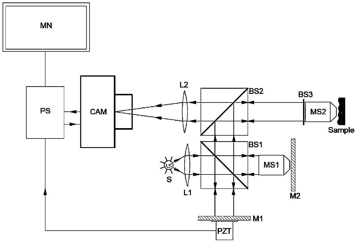
[0040] refer to figure 1 , which is shown in a structural schematic diagram of an embodiment of an interference microscope in this embodiment, specifically, an interference microscope, including:

[0041] Light source generating device, compensation interference cavity, detection arm, signal acquisition and processing unit; wherein,

[0042] The light source generator includes a light-emitting device S with a spectral width and a first lens L1. In this implementation, the light-emitting device S adopts an LED light source with a central wavelength λ0=850nm and a spectral width Δλ=30nm. The light source is collimated by the first lens L1 to become quasi-parallel light;

[0043] The compensation interference cavity includes a first beam splitter BS1, a first mirror M1, a second mirror M2, a first microscope objective MS1, and the first microscope objective MS1 is located between the first beam splitter BS1 and the second mirror M2 Between, the second reflection mirror M2 is at t...

Embodiment 2

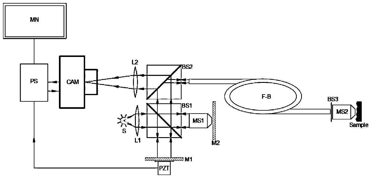
[0051] Such as figure 2 As shown, this embodiment adopts the same compensating interference cavity as that of Embodiment 1, except that the image-transmitting unit Green lens rod or the image-transmitting optical fiber bundle (F-B) is inserted into the detection arm. Both the reference light and the sample light are transmitted in the image transmission unit without changing the optical path difference, so endoscopic interference imaging can be realized. The specific imaging process is consistent with that of Embodiment 1, and will not be repeated here.


PUM

PropertyMeasurementUnit
reflectanceaaaaaaaaaa

Abstract

The invention provides an interference microscopic imaging method and an interference microscope, and particularly relates to an interference microscope which comprises a light source generation device, a compensation interference cavity, a detection arm and a signal acquisition and processing unit. The compensation interference cavity receives the light beam generated by the light source generation device and reflects the light beam into a reflected light beam to enter the detection arm; the detection arm is used for focusing the reflected light beam to form sample light and sending the sample light to the signal acquisition and processing unit; the detection unit is provided with a second microscope objective, and the second microscope objective is used for focusing light on a sample andmodulating the structure information of the sample into light to return. According to the interference microscope, the first microscope objective is inserted into the compensation interference cavityso that the reference light and the sample light only pass through the identical microscope objective in different sequences, the light paths of the sample light and the reference light are ensured to be completely equal, and unequal light paths of some points on the interference surface caused by inconsistency of passing optical devices are avoided.

Description

technical field [0001] The invention belongs to an interference microscopic imaging technology, in particular to an interference microscopic imaging method and an interference microscope. Background technique [0002] Interference microscopy is a microscope that uses coherent light interference technology. Compared with traditional microscopes, it can see the structural distribution of transparent sample tissues. It uses the principle of interference to convert the phase difference distribution into an intensity distribution for naked eye observation. The low coherence of a broad-spectrum light source also enables optical sectioning, which only images thin slices of the sample within a specific optical path range, and the slice thickness depends on the temporal coherence length of the light source. Microscopes using low-coherence interference technology have been used in integrated circuit microscopic inspection, clinical pathological diagnosis and other fields, and have th...

Claims


Application Information

Patent Timeline
Patent Type & Authority Applications(China)
IPC IPC(8): G01N21/45G01N21/01
CPCG01N21/01G01N21/45
Inventor 杜凯李俊王金玉尹韶云熊亮邹钱生王浩
Owner CHONGQING INST OF GREEN & INTELLIGENT TECH CHINESE ACADEMY OF SCI
Why Eureka
Try Eureka