Method and device for identifying laser damage of optical thin film based on polarization parameters

A technology of laser damage and optical thin film, which is applied in measuring devices, optical testing of flaws/defects, and material analysis through optical means, can solve problems such as misjudgment, and achieve wide application prospects, high discrimination accuracy, and a wide range of types Effect

Active Publication Date: 2020-07-31
XIAN TECHNOLOGICAL UNIV
View PDF5 Cites 3 Cited by
  • Summary
  • Abstract
  • Description
  • Claims
  • Application Information

AI Technical Summary

Problems solved by technology

When a strong laser acts on the surface of a thin film and a plasma flash occurs, in most cases, the compound plasma of the thin film and the atmosphere is obtained, or only the atmospheric plasma flash is obtained. To judge whether the film is damaged or not, it often causes "misjudgment" phenomenon

Method used


Image

  • Method and device for identifying laser damage of optical thin film based on polarization parameters
  • Method and device for identifying laser damage of optical thin film based on polarization parameters
  • Method and device for identifying laser damage of optical thin film based on polarization parameters

Examples


Embodiment Construction

[0022] The present invention will be described in detail below in combination with specific embodiments. These examples are for illustrating the present invention and do not limit the scope of the present invention.

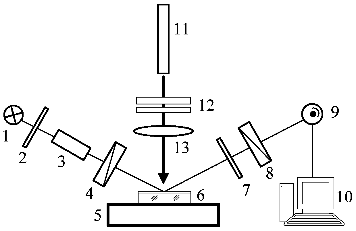
[0023] The present invention is a laser damage discrimination device for identifying optical thin films based on polarization parameters, see figure 1 A light source 1, a narrow-band filter 2 capable of monochromatic light output, a collimator 3 for collimation, and a polarizer 4 for generating linearly polarized light are sequentially arranged on one side of the incident light path of the two-dimensional workbench. Wherein, the light source 1 is an incandescent light source, and the emission spectrum is 400-700nm. Filter 2 is a narrow bandpass filter with a wavelength of 650±1nm and a half width of 5nm. The polarization azimuth angle of the polarizer is 45°, and the incident angle of the linearly polarized light generated by the polarizer 4 on the surface of t...


PUM

PropertyMeasurementUnit
angle of incidenceaaaaaaaaaa
wavelengthaaaaaaaaaa
energyaaaaaaaaaa

Abstract

The invention relates to a method and a device for identifying laser damage of an optical thin film based on polarization parameters. The method and the device overcome phenomenon of 'erroneous judgment' frequently caused by judging whether the thin film is damaged or not in the prior art, are suitable for on-line judgment of surface damage of various optical elements and coating elements in laserdamage threshold measurement, and have the characteristics of rapidness and accuracy. The device comprises a two-dimensional workbench for mounting a thin film test sample, an incident light path anda reflection light path are arranged on the two sides of the two-dimensional workbench respectively, a light source, an optical filter, a collimator and a polarizer are sequentially arranged on one side of the incident light path, a wave plate, a polarization analyzer and a photoelectric receiver are sequentially arranged on one side of the reflection light path, a laser emitting end of a high-energy laser directly faces the surface of the thin film test sample, an attenuator and a convergent lens are sequentially arranged in the laser pulse output direction of the high-energy laser, and thetwo-dimensional workbench, the wave plate, the polarization analyzer, the high-energy laser, the receiver and the attenuator are all connected to an industrial control computer.

Description

Technical field: [0001] The invention relates to a device and method for identifying damage to optical components, in particular to a method and device for identifying laser damage to optical thin films based on polarization parameters. Background technique: [0002] In a high-power, high-energy laser system, there are tens of thousands of optical thin-film elements, and the anti-laser damage performance of these thin-film elements is inseparable from the normal and effective operation of the optical system. In view of this, many optical thin film components have index requirements for laser-induced damage threshold (LIDT). Unfortunately, the current testing efficiency of LIDT is very low, the repeatability is poor, and the cost of testing is high. The main reason for these problems is the lack of fast and effective damage identification methods. Regarding the identification method of damage, the International Committee for Standardization recommends phase contrast microsc...

Claims


Application Information

Patent Timeline
Patent Type & Authority Applications(China)
IPC IPC(8): G01N21/95G01N21/21
CPCG01N21/95G01N21/211
Inventor 徐均琪苏俊宏吴慎将时凯万文博杨利红汪桂霞刘祺袁松松
Owner XIAN TECHNOLOGICAL UNIV
Why Eureka
Try Eureka