Battery pack and vehicle

A battery pack and battery technology, applied in the manufacturing of batteries, secondary batteries, and secondary batteries, can solve the problems of inability to reduce height, increase battery weight, and low space utilization, reduce overall weight and cost, and simplify batteries. Internal structure, the effect of improving space utilization

Pending Publication Date: 2020-07-31
KUNSHAN BAOTRON NEW ENERGY TECH CO LTD
View PDF0 Cites 6 Cited by
  • Summary
  • Abstract
  • Description
  • Claims
  • Application Information

AI Technical Summary

Problems solved by technology

[0002] The performance of the liquid-cooled battery module directly determines the performance of the equipment that uses the liquid-cooled battery module as the power source. However, the design of the liquid cooling system for the pouch battery is difficult, and heat-conducting plates are often used to contact the pouch battery. The plate contacts one cell or two cells share a heat conduction plate, and the heat conduction plate conducts the heat of the cell from the thickness direction of the cell. This method not only has low heat conduction efficiency, but also increases the weight of the battery, and the more cells there are , the more heat conducting plates, the more complex the assembly
Moreover, the industry expects the height of the battery pack to be continuously reduced, but the traditional pouch battery is often assembled vertically, so the height of the module is often high, and due to various requirements such as the manufacturing process and cost of the pouch battery, it cannot Reduced height, it is difficult to adapt to the requirement of reduced height of the battery system
In addition, since the length of the battery cell currently on the market is generally about 0.3 meters, there are many battery modules in the existing power battery pack, and each battery module needs to be added with a fixed structure, which is complicated to assemble. Power connections need to be made through peripheral power connectors, resulting in more battery installation structures, not only high cost, but also the overall weight of the battery pack is large and the space utilization rate is low, resulting in a low volume capacity density of the battery pack

Method used


Image

  • Battery pack and vehicle
  • Battery pack and vehicle
  • Battery pack and vehicle

Examples


Embodiment Construction

[0037] Embodiments of the present invention are described in detail below, examples of which are shown in the drawings, wherein the same or similar reference numerals designate the same or similar elements or elements having the same or similar functions throughout. The embodiments described below by referring to the figures are exemplary and are intended to explain the present invention and should not be construed as limiting the present invention.

[0038] In describing the present invention, it should be understood that the terms "center", "longitudinal", "transverse", "length", "width", "thickness", "upper", "lower", "front", " Back", "Left", "Right", "Vertical", "Horizontal", "Top", "Bottom", "Inner", "Outer", "Clockwise", "Counterclockwise", "Axial" , "radial", "circumferential" and other indicated orientations or positional relationships are based on the orientations or positional relationships shown in the drawings, which are only for the convenience of describing the ...


PUM

PropertyMeasurementUnit
lengthaaaaaaaaaa
thicknessaaaaaaaaaa
thermal conductivityaaaaaaaaaa

Abstract

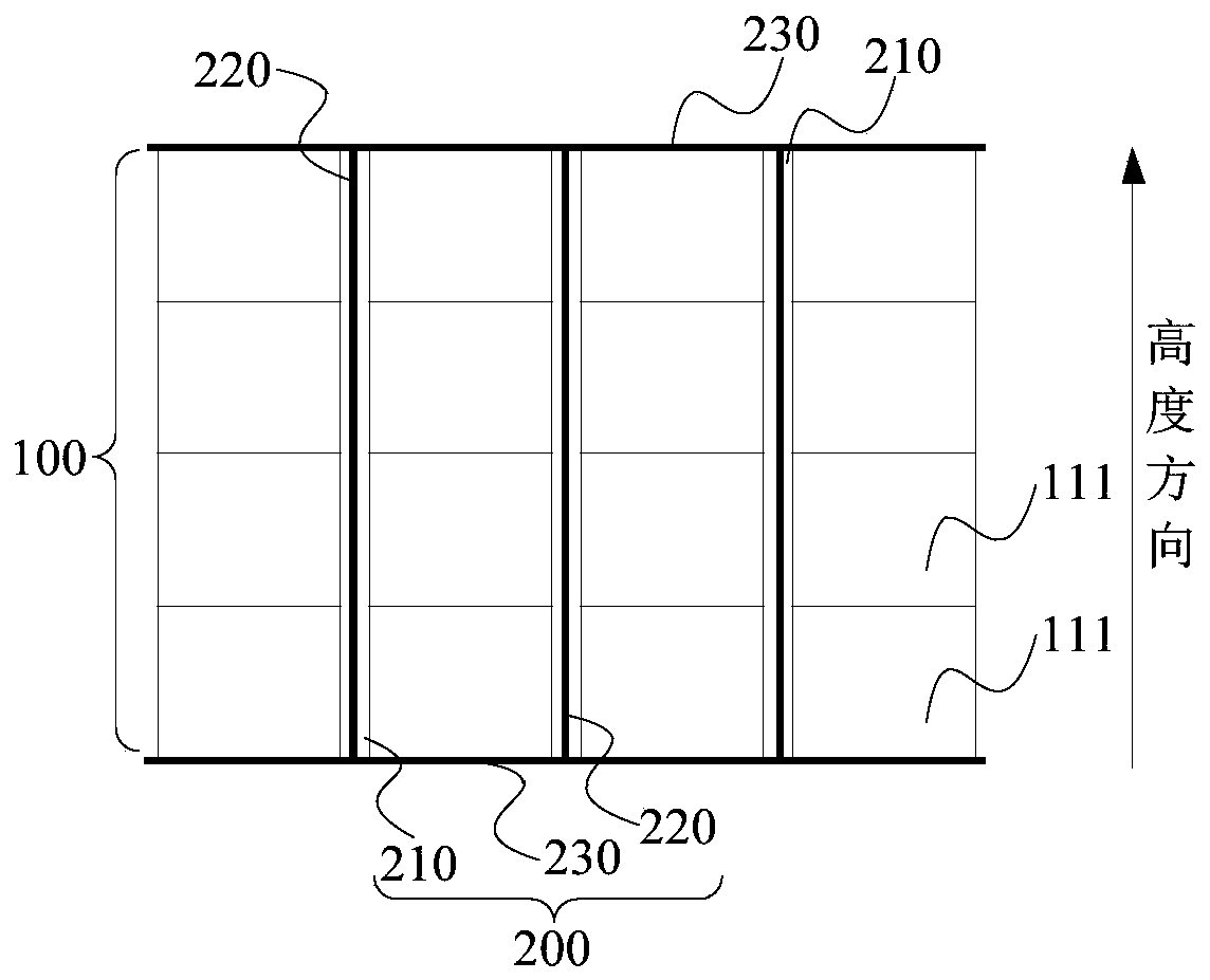
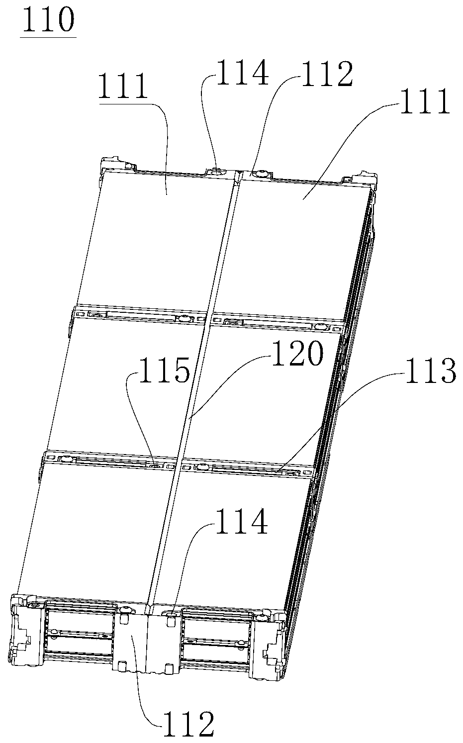
The invention discloses a battery pack and a vehicle. The battery pack comprises a battery module and a cooling device, each battery direct-connection group layer in the battery module at least comprises two battery direct-connection groups which are arranged side by side at intervals; the battery direct connection group comprises a battery cell stacking body, wherein the battery cell stack body comprises a plurality of soft package battery cells formed by series pole core groups, first pole lug brackets are arranged at two ends of each battery direct connection group, two adjacent battery direct connection groups which are arranged side by side are connected with the first pole lug brackets at the same end, and an accommodating space is defined between the two battery direct connection groups and the first pole lug brackets at the two ends; wherein the liquid cooling plate is attached to the battery direct connection group layer, the liquid cooling plate is arranged on the upper surface and/or the lower surface of the battery module, the liquid cooling plate and the accommodating space define an accommodating groove, the heat conduction plate is connected with the liquid cooling plate and inserted into the accommodating groove, the accommodating groove is sealed by another liquid cooling plate or protection plate, and heat conduction glue is arranged between the battery directconnection group and the heat conduction plate. The battery pack is simple in internal structure, high in unit volume capacity density, high in heat conduction efficiency and easy to adjust in height.

Description

technical field [0001] The invention belongs to the field of power batteries, and in particular relates to battery packs and vehicles. Background technique [0002] The performance of the liquid-cooled battery module directly determines the performance of the equipment that uses the liquid-cooled battery module as the power source. However, the design of the liquid cooling system for the pouch battery is difficult, and heat-conducting plates are often used to contact the pouch battery. The plate contacts one cell or two cells share a heat conduction plate, and the heat conduction plate conducts the heat of the cell from the thickness direction of the cell. This method not only has low heat conduction efficiency, but also increases the weight of the battery, and the more cells there are , the more the number of heat conduction plates, the more complicated the assembly. Moreover, the height of the battery pack is expected to be continuously reduced in the industry at present,...

Claims


Application Information

Patent Timeline
Patent Type & Authority Applications(China)
IPC IPC(8): H01M10/04H01M10/613H01M10/625H01M10/647H01M10/653H01M10/6554H01M10/6555H01M10/6556H01M10/6557H01M10/6567H01M2/10H01M50/249
CPCH01M10/0413H01M10/613H01M10/625H01M10/647H01M10/653H01M10/6554H01M10/6556H01M10/6555H01M10/6557H01M10/6567H01M2220/20H01M50/20Y02E60/10Y02P70/50
Inventor 杨重科冯帅赵亮李成亮翁志福
Owner KUNSHAN BAOTRON NEW ENERGY TECH CO LTD
Why Eureka
Try Eureka