Energy storage and charging integrated system

A technology of energy storage and electrical connection, applied in the integration of power network operating systems, information technology support systems, electrical components, etc., can solve problems such as high charging costs, low efficiency of internal conversion modules, and power limitations of AC power grids, and achieve breakthroughs Effects of power limitation, provision of service diversity, and energy saving

Pending Publication Date: 2020-07-31
浙江智充电力科技有限公司
View PDF0 Cites 0 Cited by
  • Summary
  • Abstract
  • Description
  • Claims
  • Application Information

AI Technical Summary

Problems solved by technology

[0003] In order to solve the problems existing in the existing charging system that the connected charging equipment is limited by the power of the AC power grid, the charging cost is high, and the use efficiency of the internal conversion module is low, the purpose of the present invention is to provide an integrated energy storage and charging system

Method used


Image

  • Energy storage and charging integrated system
  • Energy storage and charging integrated system
  • Energy storage and charging integrated system

Examples


Embodiment 1

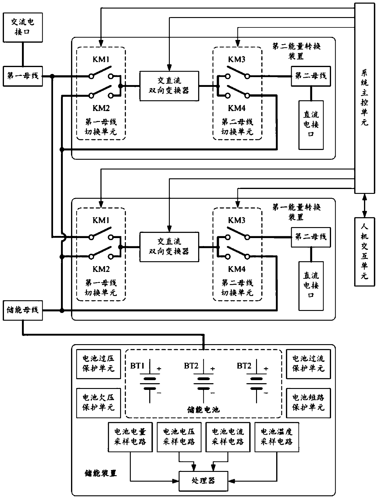
[0038] Such as Figure 1~2 As shown, the integrated energy storage and charging system provided in this embodiment includes a system main control unit, an AC power interface, a first bus, an energy storage bus, an energy storage device, and at least one energy conversion device, wherein the energy conversion The device includes a first bus switching unit, an AC-DC bidirectional converter, a second bus switching unit, a second bus and a DC interface, and the output terminals of the system main control unit are connected to the controlled end, the controlled end of the first bus switching unit, and the controlled end of the second bus switching unit; the AC power interface is electrically connected to the first connecting end of the first bus, and the first connecting end of the first bus The two connecting ends are respectively electrically connected to the first bus switching end of the first bus switching unit in each of the energy conversion devices; the energy storage devic...

Embodiment 2

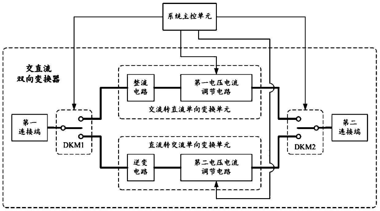
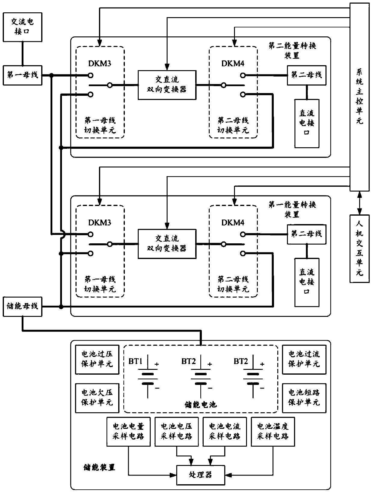
[0058] Such as image 3 As shown, this embodiment provides another integrated energy storage and charging system on the basis of the first embodiment, which is different from the technical solution described in the first embodiment in that: the first bus switching unit or The second bus switching unit includes three-state double-throw contactors DKM3 / DKM4 with controlled ends respectively connected to the main control unit of the system, wherein the first throwing end of the three-state double-throw contactors DKM3 / DKM4 As the first bus switching end of the corresponding bus switching unit, the second throwing end of the three-state double-throw contactor DKM3 / DKM4 is used as the second bus switching end of the corresponding bus switching unit, and the three-state double-throw contactor DKM3 / The common end of DKM4 corresponds to the common end of the bus switching unit. Such as image 3 As shown, through the aforementioned circuit structure, the corresponding bus switching ...

Embodiment 3

[0061] Such as Figure 4 As shown, on the basis of the first embodiment, this embodiment also provides another integrated energy storage and charging system, which differs from the technical solution described in the first embodiment in that it also includes a clean energy unit and a direct current A unidirectional converter, wherein the electric energy output terminal of the clean energy unit is electrically connected to the input terminal of the DC unidirectional converter, and the output terminal of the DC unidirectional converter is electrically connected to the first connection of the energy storage bus end. Such as Figure 4 As shown, the clean energy unit is used to convert clean energy such as solar energy, wind energy or tidal energy into electrical energy (including direct current or alternating current), which may include, but is not limited to, solar panels and / or wind generators. The DC unidirectional converter is used to convert the electric energy from the cle...


PUM


Abstract

The invention relates to the technical field of energy storage and charging, and discloses an energy storage and charging integrated system. Through the invention, on one hand, the energy storage characteristic can be utilized to reduce the power load of an AC power grid and power distribution equipment, break through the power limitation of original power distribution equipment and power grid infrastructure, and improve the use efficiency of power equipment in a charging place; and, on the other hand, the purpose of free flowing of energy among the power grid, the energy storage device and the electric vehicle can be achieved by switching multiple charging/feeding modes, multiple possibilities of energy management are provided, and the use efficiency of the internal converter is improvedto a great extent. In addition, an electric vehicle or an energy storage device can be used for reversely feeding the alternating-current power grid, therefore, electric energy is provided for alternating-current electric equipment of other users on an alternating-current power grid, an energy-saving electric vehicle battery performance detection mode is provided for the users by discharging the electric vehicle, the service diversity of charging equipment is provided, and the economic value is improved.

Description

technical field [0001] The invention belongs to the technical field of energy storage and charging, and in particular relates to an integrated energy storage and charging system. Background technique [0002] With the rapid development of society and the promotion of concepts related to green energy and environmental protection, electric vehicles are rapidly entering people's lives. However, with the rapid promotion of electric vehicles, more and more charging devices are connected to the AC grid. However, due to the limitation of the AC power grid on the power of supporting power equipment, especially the limited capacity of a single distribution transformer, the number of connected charging piles is greatly limited, especially the DC fast charging equipment for fast charging of electric vehicles. At the same time, the AC power grid has different electricity loads at different times, and there are differences in electricity prices at different times, while electric vehicle ...

Claims


Application Information

Patent Timeline
Patent Type & Authority Applications(China)
IPC IPC(8): H02J3/32H02J9/06
CPCH02J3/32H02J9/06Y02B70/30Y04S20/20
Inventor 秦继光温建阳杨伟临
Owner 浙江智充电力科技有限公司
Why Eureka
Try Eureka