High-flow hydraulic lifting power generator

A generator and large flow technology, applied in the direction of electrical components, electromechanical devices, electric components, etc., can solve the problems of poor linkage of components, large floor space, and general power generation, and achieve small footprint and large power generation , small size effect

Pending Publication Date: 2020-07-31
叶敏
View PDF0 Cites 0 Cited by
  • Summary
  • Abstract
  • Description
  • Claims
  • Application Information

AI Technical Summary

Problems solved by technology

[0003] The existing technology has the following disadvantages: During the use of the hydraulic lift generator, due to the large footprint of the hydraulic lift generator, the power generation is average, the linkage of various internal components is poor, and the power generation system is stable.

Method used


Image

  • High-flow hydraulic lifting power generator
  • High-flow hydraulic lifting power generator
  • High-flow hydraulic lifting power generator

Examples


Embodiment Construction

[0024] The implementation mode of the present invention is illustrated by specific specific examples below, and those who are familiar with this technology can easily understand other advantages and effects of the present invention from the contents disclosed in this description. Obviously, the described embodiments are a part of the present invention. , but not all examples. Based on the embodiments of the present invention, all other embodiments obtained by persons of ordinary skill in the art without making creative efforts belong to the protection scope of the present invention.

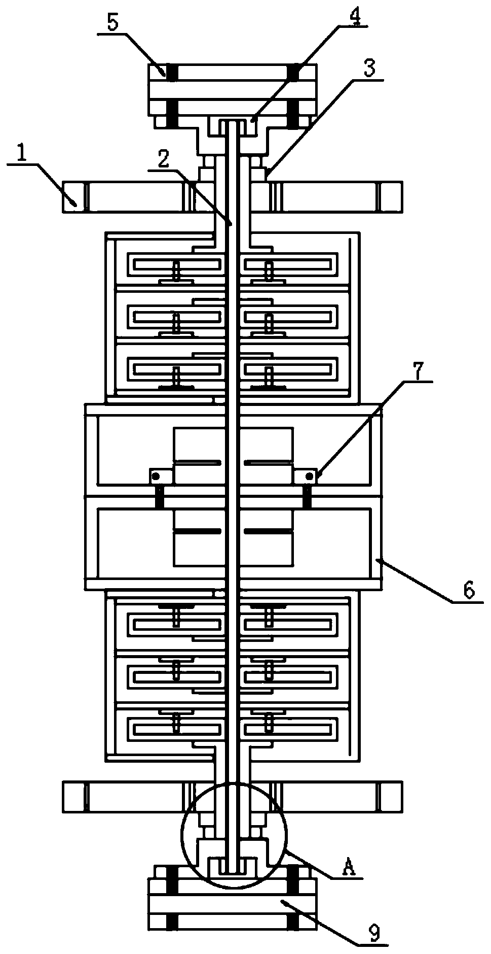
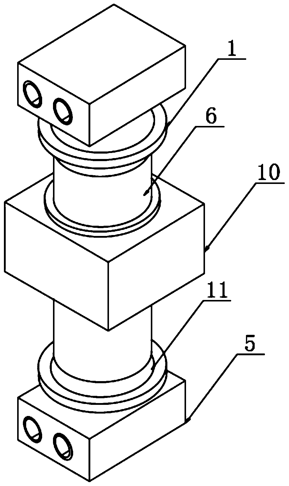
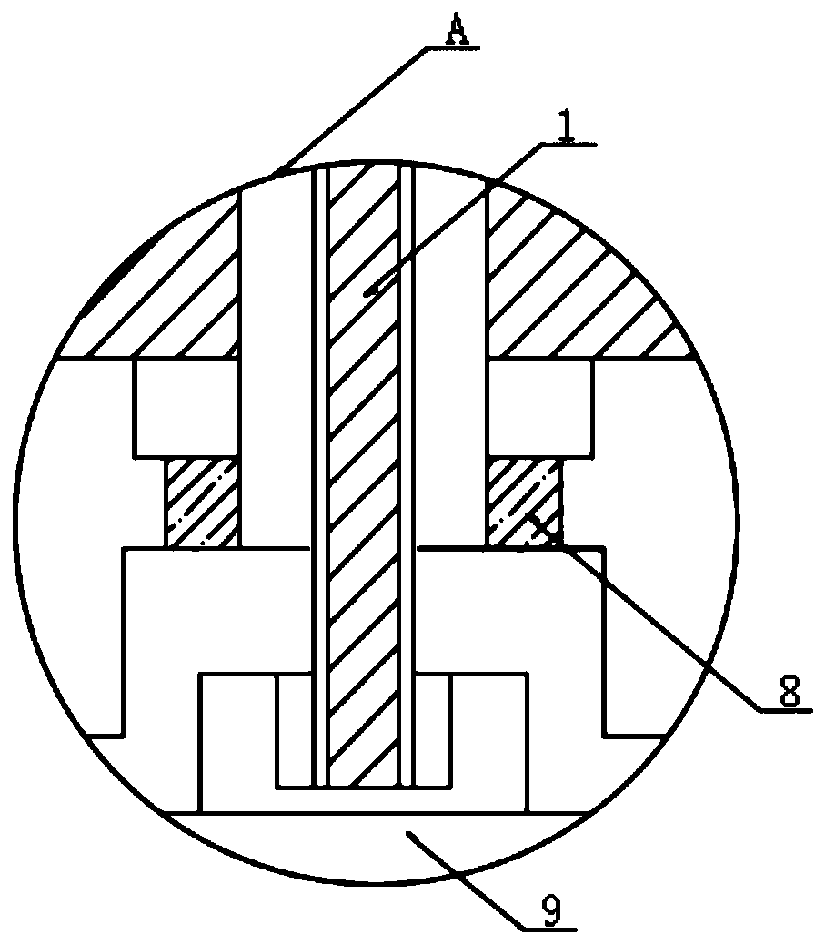
[0025] Refer to the attached Figure 1-7 , a large-flow hydraulic power-lifting generator in this embodiment includes a bridge starting tooth 1, a column shaft 2, a bearing seat 3, an inner nut 4, a guide rail block 5, a generator seat plate 6, a motor 7, and a plane thrust bearing 8. Central shaft 9, generator box 10, large plate gear 11, column shaft 12, hydraulic power rod 13, end face bearin...


PUM


Abstract

The embodiment of the invention discloses a high-flow hydraulic lifting power generator, and particularly relates to the field of power generators. The high-flow hydraulic lifting power generator comprises a bridge starting gear, wherein a guide rail block is fixedly arranged above the bridge starting gear, and a power generator seat plate is fixedly arranged below the bridge starting gear. According to the invention, a 01 hydraulic station in hydraulic force lifting equipment drives a 02 hydraulic power pump to drive a 03 helical gear, a 04 two-time speed reduction planet is pushed through six times of lifting force, the bridge starting gear is pushed through two times of lifting force, a 05 large gear is linked with the bridge starting gear of the speed-increasing generator, planetary gears at the upper end and the lower end of the speed-increasing generator are started to increase speed by 5 times, the rotating speed is increased to 2250 revolutions per minute from 90 revolutions per minute under the driving of a speed increaser, and independent acting, independent power generation and input into a grid-connected filtering frequency conversion shunt of a control system are achieved, so that power sources can be effectively saved, the working efficiency of the generator is improved, and high practicability is achieved.

Description

technical field [0001] Embodiments of the present invention relate to the field of generators, in particular to a large-flow hydraulic lift generator. Background technique [0002] Like other types of generators, the hydraulic deceleration and force-lifting generator has a common rule, that is, it needs power outside the machine as a power source for self-generating power generation. Commonly known as the driving force, such as: thermal power generation depends on the steam turbine to drive the generator to generate electricity, wind power generation relies on the airflow tide to drive the wind blades and then drive me to drive the turbine to rotate the generator to generate electricity, etc. The hydraulic deceleration lift generator uses an electric motor The power is converted into power, and the hydraulic power is used to decelerate and expand the power to drive the generator to generate electricity. [0003] The prior art has the following disadvantages: in the process ...

Claims


Application Information

Patent Timeline
Patent Type & Authority Applications(China)
IPC IPC(8): H02K7/18H02K5/24H02K5/173
CPCH02K5/1732H02K5/24H02K7/1807
Inventor 叶敏
Owner 叶敏
Why Eureka
Try Eureka