Continuous piercing machine for auricularia fungus bags

A punching machine and agaric fungus technology, applied in horticulture, botany equipment and methods, plant cultivation, etc., can solve the problems of low punching efficiency, time-consuming and labor-intensive punching of fungus bags, etc., and achieve the effect of improving the punching efficiency

Inactive Publication Date: 2020-08-04
陈翔
View PDF11 Cites 6 Cited by
  • Summary
  • Abstract
  • Description
  • Claims
  • Application Information

AI Technical Summary

Problems solved by technology

[0006] In order to overcome the time-consuming and labor-intensive and low-efficiency shortcomings of manual puncturing of agaric fungus bags, the technical problem to be solved by the present invention is to provide a method that can continuously perform puncturing, improve puncturing efficiency, and save time and effort. Auricularia bag continuous punching machine

Method used


Image

  • Continuous piercing machine for auricularia fungus bags
  • Continuous piercing machine for auricularia fungus bags
  • Continuous piercing machine for auricularia fungus bags

Examples


Embodiment 1

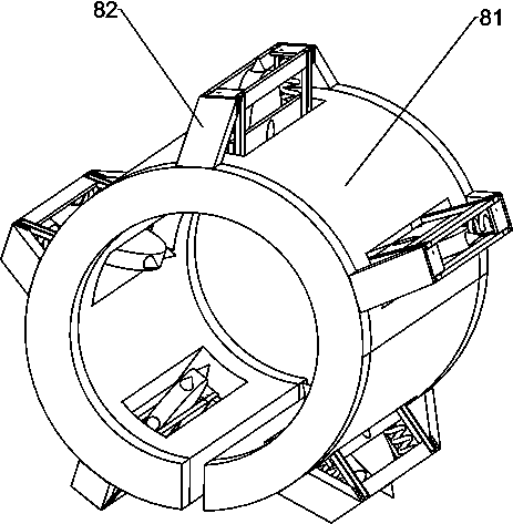
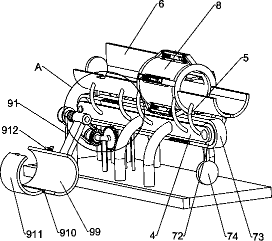
[0025] A continuous punching machine for fungus bags, such as Figure 1-5 As shown, it includes a base 1, a bracket 2, a first connecting column 3, a main body mounting plate 4, a second connecting column 5, a guide rail 6, a moving mechanism 7 and a punching mechanism 8, and the left side of the front side of the top of the base 1 is connected with a The bracket 2, the left and right sides of the top of the base 1 are connected with two first connecting columns 3, the tops of the two first connecting columns 3 on the left and right sides are connected with a main body mounting plate 4, and the two main body mounting plates 4 are connected to each other. A moving mechanism 7 is installed, and the outer surface of the main body mounting plate 4 is connected with a plurality of second connecting columns 5, and guide rails 6 are connected between the tops of the plurality of second connecting columns 5, and the bottom of the guide rails 6 has a through groove, and the guide rails ...

Embodiment 2

[0030] On the basis of Example 1, such as figure 1 , figure 2 with Image 6 As shown, also includes feeding mechanism 9, and feeding mechanism 9 includes fixed mounting block 91, rotating shaft 92, transmission belt group 93, bevel gear 94, transmission gear 95, V-shaped fixed frame 96, locking tooth group 97, torque Spring 98, swing arm 99, connecting shaft 910, arc cover plate 911, buckle 912 and trip lever 913, the top of base 1 on the right side of support 2 is connected with fixed installation block 91, and the top of base 1 on the left side of fixed installation block 91 A V-shaped fixed mount 96 is connected, and the left side of the V-shaped fixed mount 96 is rotatably connected with a transmission gear 95, and the front side of the V-shaped fixed mount 96 is rotatably connected with a bevel gear 94, and the bevel gear 94 meshes with the transmission gear 95. The right side of transmission belt 73 is connected with two latching tooth groups 97, and latching tooth gr...

Embodiment 3

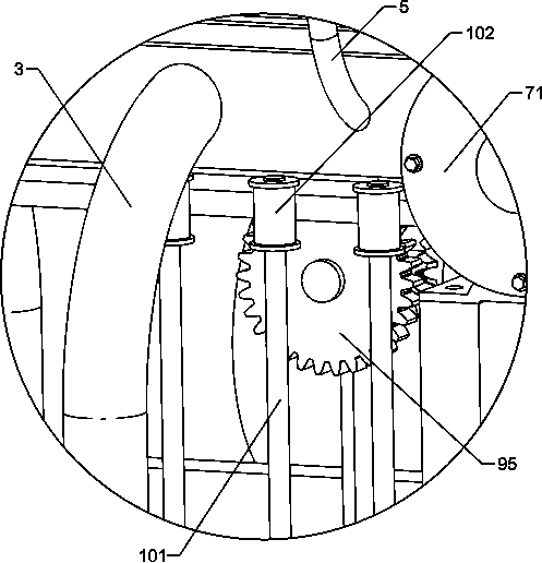
[0033] On the basis of Example 2, such as figure 1 with Figure 7 As shown, it also includes a limit structure 10, the limit structure 10 includes a fixed rod 101 and a pulley 102, a plurality of fixed rods 101 are connected to the top of the base 1 on the left side of the V-shaped fixed frame 96, and the top of the fixed rod 101 is rotatably connected A pulley 102 is provided, and the pulley 102 is in contact with the left side of the drive belt 73 .

[0034] The pulley 102 is in contact with the left side of the transmission belt 73, which can prevent the transmission belt 73 from shaking left and right when it is stressed, so that the locking tooth set 97 and the transmission gear 95 can be tightly meshed.


PUM


Abstract

The invention relates to a piercing machine, in particular to a continuous piercing machine for auricularia fungus bags, and aims to solve the technical problem of how to provide a continuous piercingmachine for auricularia fungus bags capable of continuously carrying out piercing, improving the piercing efficiency and saving both time and labor. In order to solve the technical problem, the invention provides the continuous piercing machine for the auricularia fungus bags. The continuous piercing machine comprises a base, first connecting posts, main body mounting plates, a travel mechanism and second connecting posts, wherein one side of the top of the base is connected with a bracket; two sides of the top, far away from the bracket, of the base are connected with the first connecting posts; each first connecting post is connected with one main body mounting plate; the travel mechanism is arranged between the main body mounting plates; and the outer side surface of each main body mounting plate is connected with a plurality of second connecting posts. A transmission belt of the continuous piercing machine clockwise rotates and can continuously convey the auricularia fungus bags backwards through push plates, and punching wheels can continuously pierce the auricularia fungus bags moving backwards.

Description

technical field [0001] The invention relates to a punching machine, in particular to a continuous punching machine for fungus bags. Background technique [0002] Fungus is an aerobic fungus, in the course of life activities, it continuously absorbs oxygen and emits carbon dioxide. When fungus mycelium is short-term hypoxic, although it can temporarily maintain life activities with the help of zymolysis, it consumes a lot of nutrients, and the mycelia will gradually weaken and age, shortening the life span. When mycelium is severely hypoxic, its growth will be hindered, and at the same time, it is easy to infect miscellaneous bacteria because it is difficult for mycelium to cover the compost. Therefore, during the cultivation stage, the fungus sticks must be punctured, through which the mycelium can fully absorb oxygen, make its growth active, strengthen its metabolic activity, and ensure the healthy growth of mycelia. [0003] At present, the puncture of the fungus bag is ...

Claims


Application Information

Patent Timeline
Patent Type & Authority Applications(China)
IPC IPC(8): A01G18/60
CPCA01G18/60
Inventor 陈翔
Owner 陈翔
Why Eureka
Try Eureka