

Feeding device and cooking robot
The technology of a feeding device and a barrel, which is applied to cooking utensils, household appliances, applications, etc., can solve the problems of low feeding accuracy, and achieve the effect of solving low precision and accurate feeding.
- Summary
- Abstract
- Description
- Claims
- Application Information
AI Technical Summary
Problems solved by technology
Method used
Image

Examples
Embodiment 1
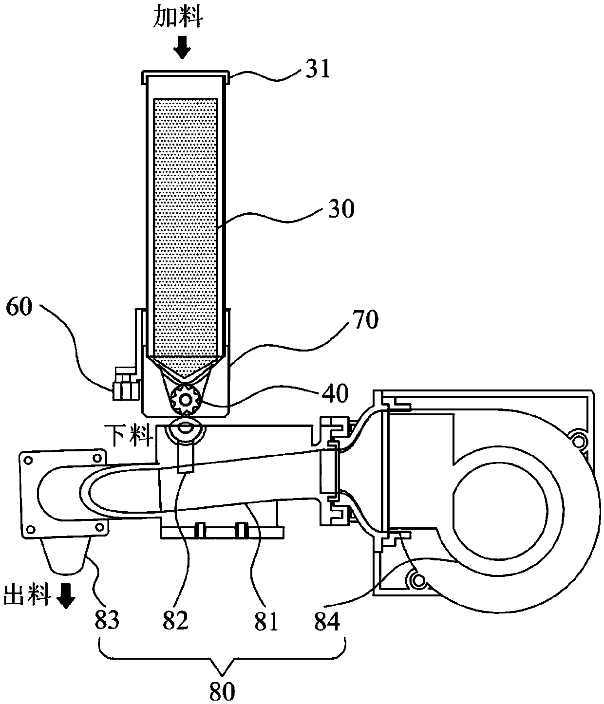
[0040] Such as figure 1 Shown is a schematic structural view of the feeding device provided by the embodiment of the present invention.
[0041] refer to Figure 1-6 As shown, the feeding device provided by the present invention includes a base 20, a barrel 30 arranged on the base 20, a turbine 40 arranged at the bottom of the barrel 30, a power assembly 50 for driving the turbine 40 to rotate, and a barrel 30 arranged on the barrel 30. The metering assembly 60.
[0042] Wherein, the feeding device is used for adding materials. Specifically, in this embodiment, the feeding device is suitable for the technical field of the kitchen, and is used for adding an appropriate amount of materials during cooking. It can be understood that in other embodiments of the invention , the feeding device can also be used in other technical fields to realize the appropriate addition of materials, which is not limited here.
[0043] Wherein, useful materials are contained in the barrel 30, and...
Embodiment 2
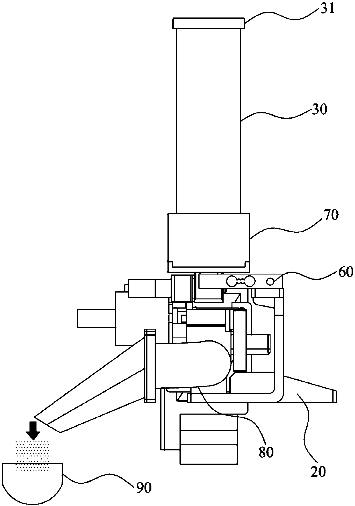
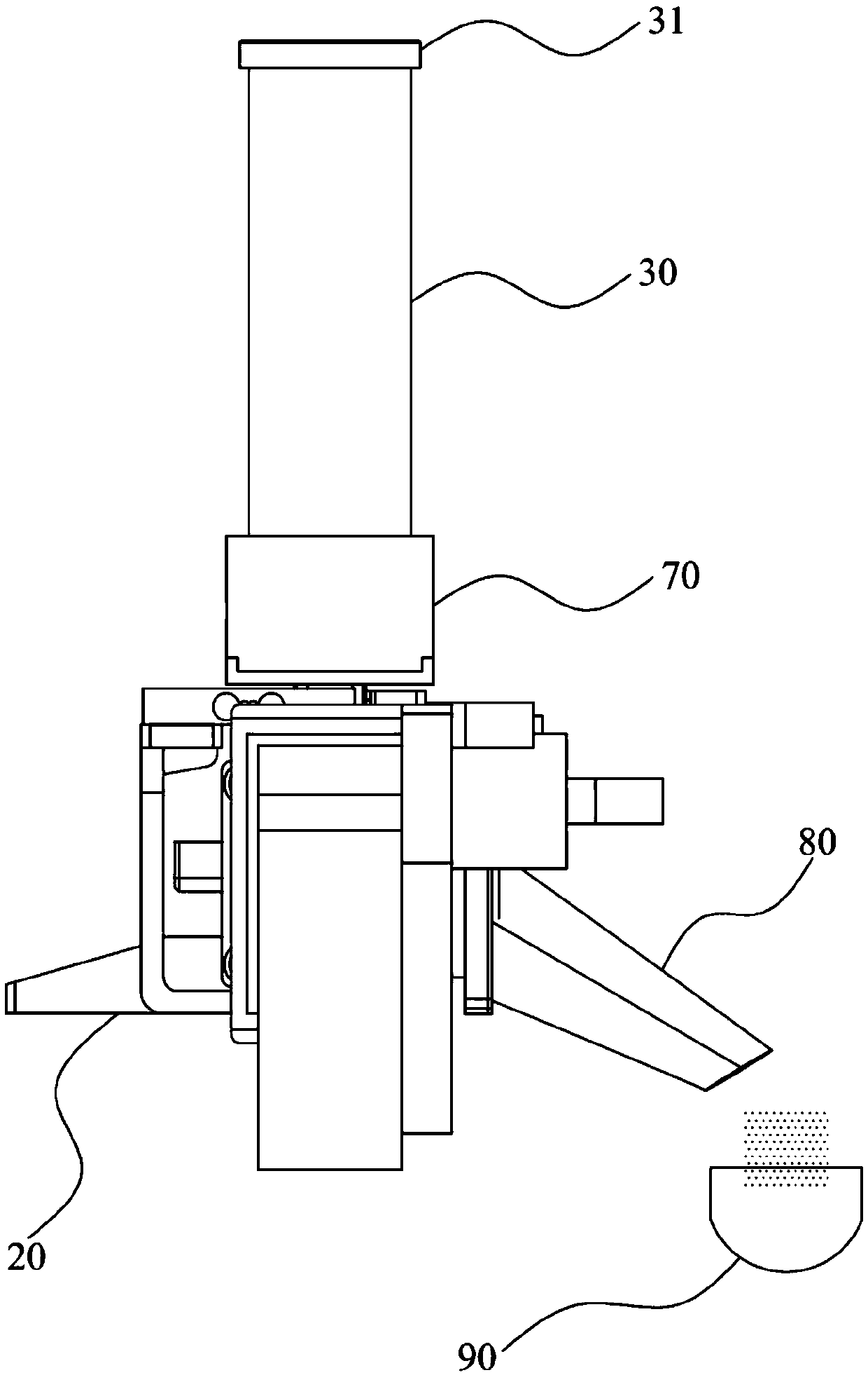
[0063] Such as Figure 7-Figure 9 Shown is a schematic view of the structure of the feeding device provided by the preferred embodiment of the present invention. Its realization principle and technical effect are the same as those of Embodiment 1. For a brief description, the details not mentioned in the embodiment of the present invention can be referred to in Embodiment 1. Corresponding content.
[0064] The difference is that, in one embodiment of the present invention, several barrels 30 are arranged on the base. Each of its barrels 30 can contain materials. Specifically, in this embodiment, the number of barrels 30 is six. It can be understood that in other embodiments of the present invention, the number of barrels 30 can also be For others, it is not limited here.
[0065] Further, the number of metering assemblies 60 is the same as the number of barrels 30, each barrel 30 is correspondingly provided with a feeding fixing seat 70, and each barrel 30 is connected to a ...
Embodiment 3
[0070] The embodiment of the present invention also provides a cooking robot, which includes the feeding device as described in the above embodiment. This cooking robot uses the feeding device of the above-mentioned embodiment, so that it can measure the output amount of the material thrown from the barrel through the set metering assembly, and realize the discharge through the work of the turbine, so that it can realize accurate Add ingredients to improve the accuracy of ingredients used by cooking robots.
PUM
 Abstract
Description
Claims
Application Information