Sludge discharge device for sewage treatment

A sludge discharge device and sewage treatment technology, applied in water/sewage treatment, water/sewage treatment equipment, water/sludge/sewage treatment, etc. High mud efficiency, improve filtration efficiency and increase the effect of contact area

Active Publication Date: 2020-08-04
GUANGZHOU BAOYUAN ECONOMY ENVIRONMENTAL POLLUTION SCI & TECH CO LTD
View PDF8 Cites 3 Cited by
  • Summary
  • Abstract
  • Description
  • Claims
  • Application Information

AI Technical Summary

Problems solved by technology

[0004] The purpose of the present invention is to provide a sludge discharge device for sewage treatment, which includes a box body, a filter cavity is arranged in the box body, a water inlet is arranged in the middle of the right side wall of the box body, the water inlet is connected with the filter cavity, and the box body There is a mud discharge chamber on the left side for mud discharge. The mud discharge chamber is connected with the filter chamber. The problem of incomplete mud discharge

Method used


Image

  • Sludge discharge device for sewage treatment
  • Sludge discharge device for sewage treatment
  • Sludge discharge device for sewage treatment

Examples


Embodiment 1

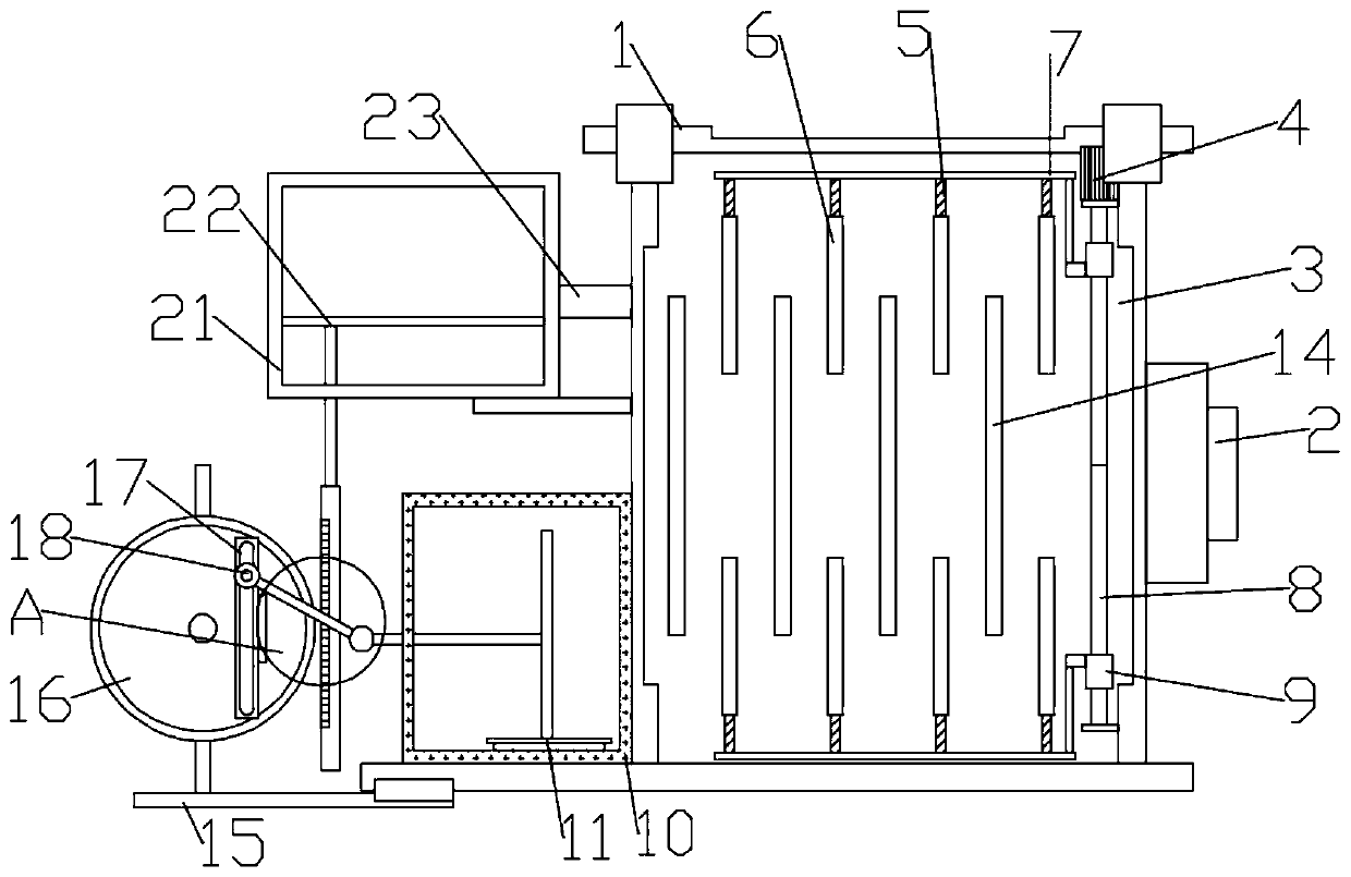
[0022] Such as figure 1 As shown, in the embodiment of the present invention, a sludge discharge device for sewage treatment includes a box body 1, a filter chamber 3 is provided in the box body 1, a water inlet 2 is provided at the middle position of the right side wall of the box body 1, and the water inlet 2 communicates with the filter chamber 3, and the left side of the box body 1 is provided with a mud discharge chamber 10 for mud discharge. with filter components;

[0023] The filter assembly includes a lifting filter screen 6 and a fixed filter screen 14, the lifting filter screen 6 is symmetrically arranged about the horizontal central axis of the filter chamber 3, and the lifting filter screen 6 is fixedly installed on the lifting filter screen mounting seat 5, and the lifting filter screen mounting seat 5 The lifting plate 7 that is used to adjust the position of the lifting filter screen 6 is fixedly connected, and the lifting plate 7 is fixedly connected with a d...

Embodiment 2

[0028] Such as figure 1 As shown, in the embodiment of the present invention, a sludge discharge device for sewage treatment includes a box body 1, a filter chamber 3 is provided in the box body 1, a water inlet 2 is provided at the middle position of the right side wall of the box body 1, and the water inlet 2 communicates with the filter chamber 3, and the left side of the box body 1 is provided with a mud discharge chamber 10 for mud discharge. with filter components;

[0029] The filter assembly includes a lifting filter screen 6 and a fixed filter screen 14, the lifting filter screen 6 is symmetrically arranged about the horizontal central axis of the filter chamber 3, and the lifting filter screen 6 is fixedly installed on the lifting filter screen mounting seat 5, and the lifting filter screen mounting seat 5 The lifting plate 7 that is used to adjust the position of the lifting filter screen 6 is fixedly connected, and the lifting plate 7 is fixedly connected with a d...


PUM


Abstract

The invention discloses a sludge discharge device for sewage treatment, which belongs to the technical field of sewage treatment, and solves the problem of incomplete sludge discharge caused by easy blockage of sludge in an existing device. The device is technically characterized by comprising a box body, a filtering cavity is formed in the box body, a water inlet is formed in the middle of the right side wall of the box body, the water inlet is communicated with a filtering cavity, a sludge discharging cavity used for discharging sludge is formed in the left side of the box body, the sludge discharging cavity is communicated with the filtering cavity, a sludge discharging assembly is arranged in the sludge discharging cavity, and a filtering assembly is arranged in the filtering cavity; according to the embodiment of the invention, the sludge discharge assembly is arranged, so that accumulation of sludge in the filter cavity is avoided, the sludge discharge efficiency is high, rapid filtration of sewage is realized through the arrangement of the filter assembly, a contact area between the filter assembly and the sewage is increased, and the filter efficiency is improved.

Description

technical field [0001] The invention relates to the technical field of sewage treatment, in particular to a sludge discharge device for sewage treatment. Background technique [0002] Sewage treatment has attracted more and more people's attention. The existing sewage treatment methods include physical precipitation, chemical precipitation, biodegradation, etc., but no matter which method is used for sewage treatment, in the process of sewage treatment , the bottom of the sewage treatment device will accumulate a large amount of sludge after a period of time, and in order to ensure the normal and effective sewage treatment, users often need to clean the sludge inside the sewage treatment device. [0003] Chinese patent CN210438594U discloses a sludge discharge device for sewage treatment, which relates to the technical field of sewage treatment. It includes the body and supporting legs. The supporting legs are located at the bottom of the body. The top of the body is fixedl...

Claims


Application Information

Patent Timeline
Patent Type & Authority Applications(China)
IPC IPC(8): C02F1/00B01D36/02
CPCB01D36/02C02F1/001C02F2201/002C02F2301/08C02F2303/14
Inventor 马帅
Owner GUANGZHOU BAOYUAN ECONOMY ENVIRONMENTAL POLLUTION SCI & TECH CO LTD
Why Eureka
Try Eureka