Efficient dyeing device for textile fabric production line

A technology for textile fabrics and dyeing devices, which is applied in the direction of processing textile material equipment configuration, textile material processing, and processing textile material carriers, etc., can solve the problems of poor dyeing effect and low efficiency, and achieve product quality improvement, gap expansion, and dyeing good effect

Inactive Publication Date: 2020-08-04
韩兰珍
View PDF4 Cites 6 Cited by
  • Summary
  • Abstract
  • Description
  • Claims
  • Application Information

AI Technical Summary

Problems solved by technology

[0005] The purpose of the present invention is to solve the problems of low efficiency and poor dyeing effect, and provide a high-efficiency dyeing device for textile fabric production line with high efficiency and good dyeing effect

Method used


Image

  • Efficient dyeing device for textile fabric production line
  • Efficient dyeing device for textile fabric production line
  • Efficient dyeing device for textile fabric production line

Examples


Embodiment 1

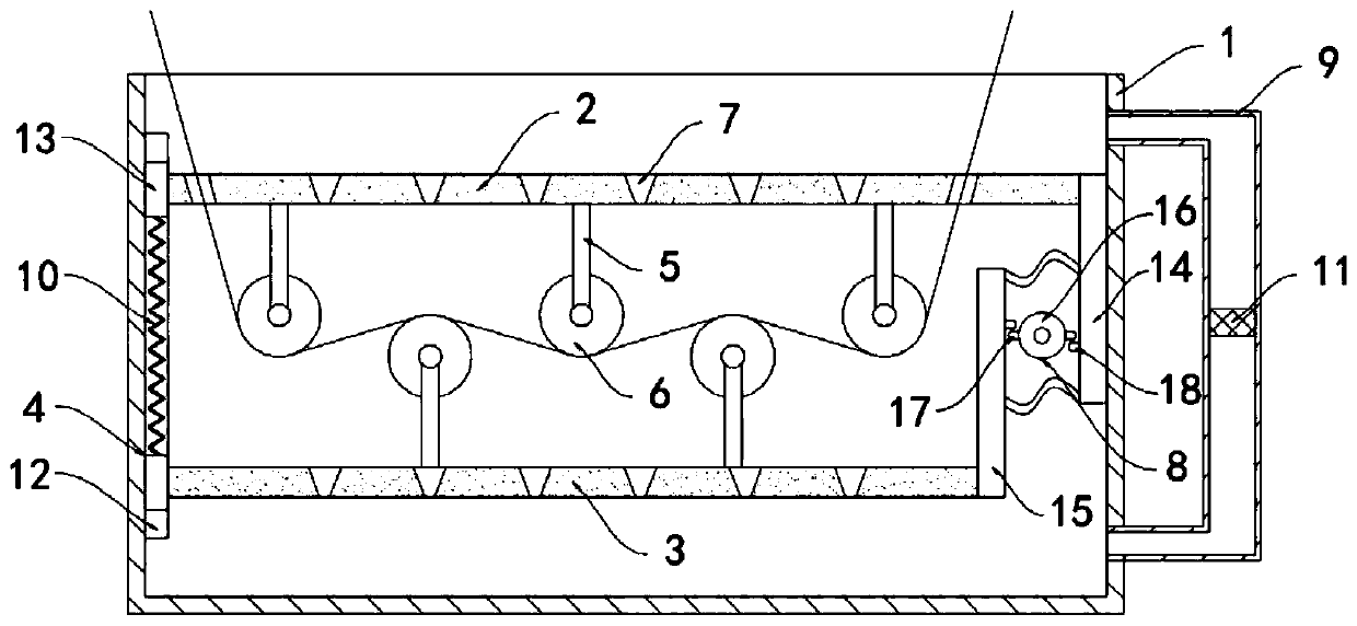
[0020] Such as figure 1 As shown, a high-efficiency dyeing device for a textile fabric production line includes a dyeing tank 1, a horizontally arranged upper sliding plate 2 slides in the dyeing tank 1, and a lower sliding plate 3 parallel to it is provided below the upper sliding plate 2. The sliding plate 2 and the lower sliding plate 3 are all slidably connected with the inner side wall of the dyeing tank 1 through the sliding mechanism 4. The sliding mechanism 4 includes a slide rail 12 fixedly installed on the inner side wall of the dyeing tank 1, and two slide rails 12 are slidably connected. The slider 13 is fixedly connected by the compression spring 10 between the two sliders 13, and the two sliders 13 are fixed to the upper sliding plate 2 and the lower sliding plate 3 respectively.

[0021] The lower surface of the upper sliding plate 2 and the upper surface of the lower sliding plate 3 are fixedly equipped with a plurality of support rods 5, and the plurality of s...

Embodiment 2

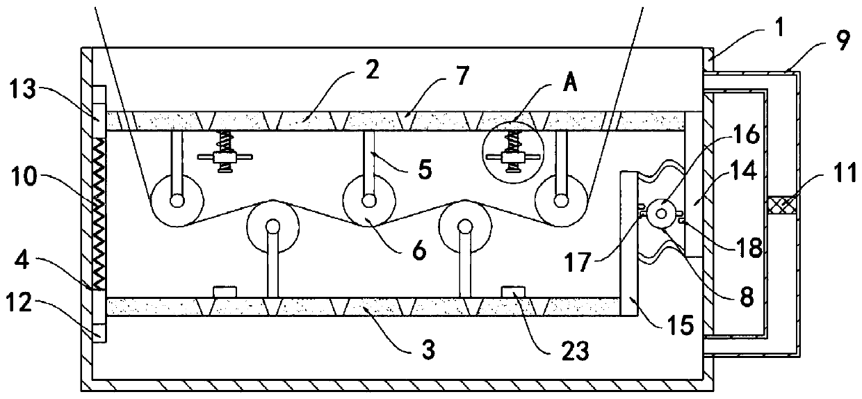
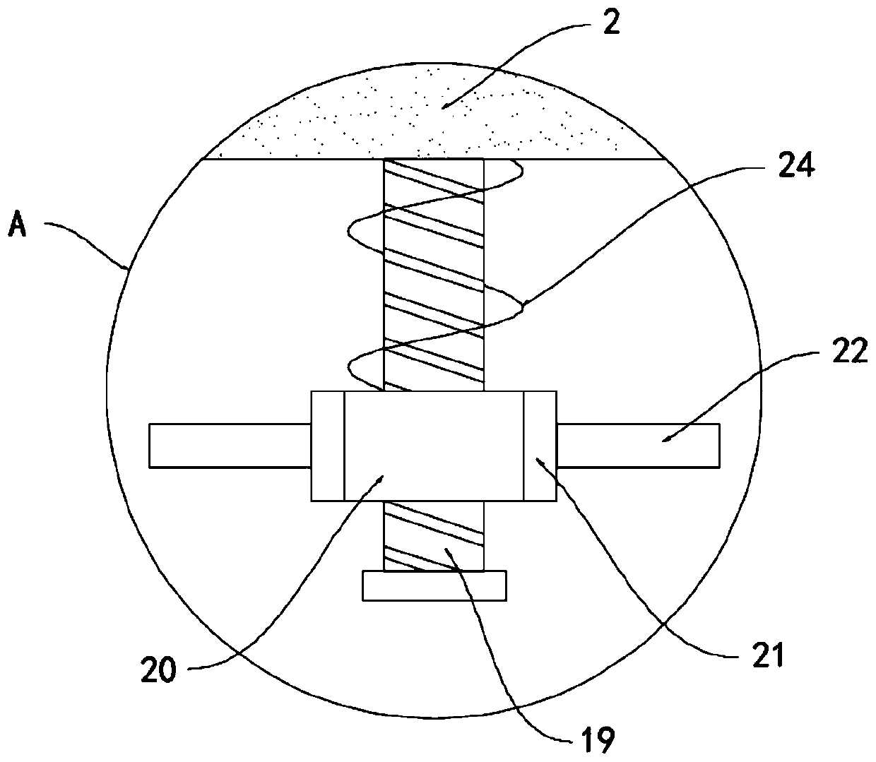
[0027] Such as Figure 2-3 As shown, the difference between this embodiment and Embodiment 1 is that: the lower surface of the upper sliding plate 2 is fixedly connected with a threaded rod 19, the external thread of the threaded rod 19 is sleeved with a threaded barrel 20, and the threaded rod 19 is a coarse thread. The thread lift angle is greater than the equivalent friction angle of the screw pair, and does not have self-locking properties. The threaded cylinder 20 is rotationally connected with the upper sliding plate 2 through the return spring 24. The outer fixed sleeve of the threaded cylinder 20 is connected with a permanent magnet ring 21, A plurality of stirring rods 22 are installed on the side wall of the sidewall, and the upper surface of the lower sliding plate 3 is provided with a magnet block 23 matched with the permanent magnet ring 21, and the magnet block 23 and the permanent magnet ring 21 repel each other with the same pole.

[0028]In this embodiment, th...


PUM


Abstract

The invention belongs to the technical field of textile equipment, and particularly relates to an efficient dyeing device for a textile fabric production line. The equipment comprises a dyeing tank, ahorizontally arranged upper sliding plate is arranged in the dyeing tank in a sliding manner, and a lower sliding plate parallel to the upper sliding plate is arranged below the upper sliding plate;the upper sliding plate and the lower sliding plate are both slidably connected with the inner side wall of the dyeing tank through sliding mechanisms, a plurality of supporting rods are fixedly mounted on the lower surface of the upper sliding plate and the upper surface of the lower sliding plate correspondingly, the supporting rods are distributed at equal intervals in a staggered mode, and guide rollers are mounted at the other ends of the supporting rods; through holes are formed in the upper sliding plate and the lower sliding plate in a penetrating mode, the diameter of an opening in the upper end of each through hole is larger than that of an opening in the lower end of each through hole, and a driving mechanism used for driving the upper sliding plate and the lower sliding plate to slide is arranged in the dyeing tank. Dye can be promoted to alternately flow in gaps between warps and wefts of the textile fabric from top to bottom, the permeation effect of the dye in the textile fabric is improved, and the dyeing effect is better.

Description

technical field [0001] The invention belongs to the technical field of textile equipment, and in particular relates to a high-efficiency dyeing device for a textile fabric production line. Background technique [0002] There are two traditional dyeing methods for textile fabrics, one is dip dyeing, in which the textile is dipped in the dye solution, and the dye is dyed on the fiber and fixed in the fiber after a certain period of time; the other is pad dyeing, in which the textile fabric is After a brief immersion in the dye solution, the rollers are used to squeeze the dye solution into the interstitial space of the fabric, and remove the excess dye solution, so that the dye is evenly distributed on the fabric. Finished during processing such as steaming or baking. [0003] However, these two dyeing methods have disadvantages. Exhaust dyeing is only suitable for intermittent production, and the dyeing time is long and the production efficiency is low; the dyeing efficiency...

Claims


Application Information

Patent Timeline
Patent Type & Authority Applications(China)
IPC IPC(8): D06B3/10D06B23/04D06B23/20
CPCD06B3/10D06B23/04D06B23/20D06B23/205
Inventor 韩兰珍
Owner 韩兰珍
Why Eureka
Try Eureka