Silicon controlled rectifier module

A backplane and red copper technology, applied in the direction of semiconductor/solid-state device components, semiconductor devices, electrical components, etc., can solve the problems of shortened service life, high stress, easy to damage chips, etc., and achieve the effect of reducing stress and shortening service life

Pending Publication Date: 2020-08-04
黄山市阊华电子有限责任公司
View PDF0 Cites 2 Cited by
  • Summary
  • Abstract
  • Description
  • Claims
  • Application Information

AI Technical Summary

Problems solved by technology

[0004] The purpose of the present invention is to provide a thyristor module, which solves the problem that the existing thyristor module is connected through a bridge, which has high stress, easy damage to the chip, and shortened service life.

Method used


Image

  • Silicon controlled rectifier module
  • Silicon controlled rectifier module

Examples


Embodiment Construction

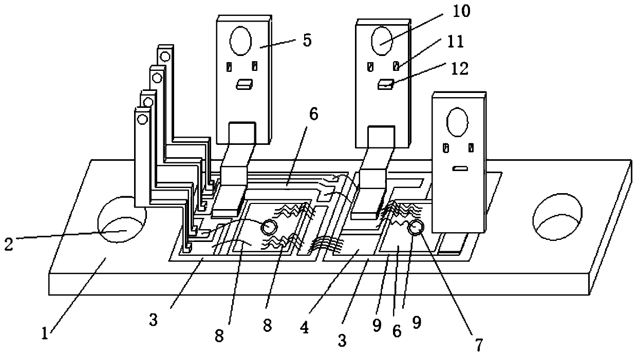
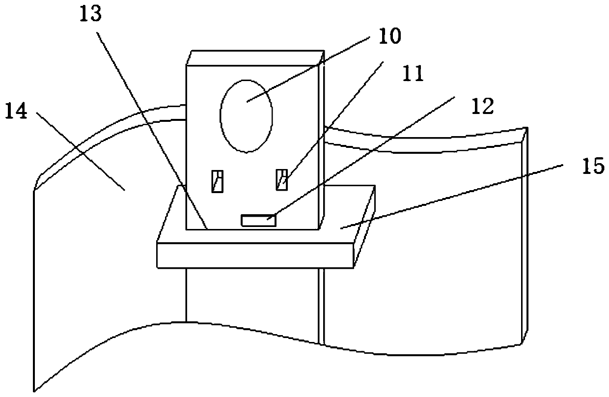
[0018] Examples such as figure 1 , figure 2 The silicon controlled rectifier module shown includes a copper base plate 1, a housing 14 arranged on the copper base plate 1, an external connection hole 2 is respectively provided at the left and right ends of the copper base plate 1, and the copper base plate 1 is located between the two external connection holes 2 Two ceramic sheets 3 are provided, and a set of copper-clad areas 4 are arranged on the two ceramic sheets 3 respectively. The copper-clad area 4 is provided with a set of lead-out electrode sheets 5 and two chips 6 according to the controllable rectification circuit, and the middle of the chip 6 is set There is a gate point 7, and an aluminum wire 8 is bonded between the chip 6 and the copper-clad area 4, and between the gate point 7 and the copper-clad area 4. The bonding of the aluminum wire 8 is realized by a wire punching machine.

[0019] In describing the present invention, it is to be understood that the ter...


PUM

PropertyMeasurementUnit
Diameteraaaaaaaaaa

Abstract

The invention relates to a silicon controlled rectifier module. The silicon controlled rectifier module comprises a red copper bottom plate and a shell which is arranged on the red copper bottom plate; the left end and the right end of the red copper bottom plate are each provided with an external hole; the red copper bottom plate is provided with two ceramic chips between the two external holes;the two ceramic chips are respectively provided with a group of copper-clad areas; each copper-clad area is provided with a group of extraction electrode plates and two chips according to a controllable rectification circuit, and gate poles are arranged in the middle of the chips; and aluminum wires are bonded between the chips and the copper-clad areas and between the gate poles and the copper-clad areas. The silicon controlled rectifier module can effectively solve the problems that an existing silicon controlled rectifier module is connected through a connecting bridge, stress is high, a chip is prone to damage, and the service life is shortened.

Description

technical field [0001] The invention relates to a thyristor module. Background technique [0002] In the prior art, the structure of the thyristor rectifier module basically includes a shell, and components such as lead-out electrode sheets, copper connecting plates, bridges, controllable chips, ceramic copper-clad laminates, and copper bottom plates set in the shell, At the same time, lead out electrode sheets, copper connection plates, connecting bridges, controllable chips, ceramic copper clad laminates and copper bottom plate groups are encapsulated in the housing by epoxy resin. [0003] However, the connection through the bridge method has the problems of high stress, easy damage to the chip, and shortened service life. Contents of the invention [0004] The object of the present invention is to provide a thyristor module, which solves the problems that existing thyristor modules are connected through a bridge, which has high stress, easily damaged chips, and shorte...

Claims


Application Information

Patent Timeline
IPC IPC(8): H01L25/07H01L29/74H01L23/29H01L23/49
CPCH01L29/74H01L25/072H01L23/49H01L23/291H01L24/49H01L2224/4905H01L2224/4912H01L2224/495H01L2924/01013
Inventor 凌定华洪国东戴国中方新建
Owner 黄山市阊华电子有限责任公司
Why Eureka
Try Eureka