Bone drill sighting device

A technology of aimer and bone drill, applied in the direction of bone drill guidance, medical science, surgery, etc., can solve the problems of poor surgical effect, difficult to accurately control the position of bone blocks, and difficult to accurately determine the position of the preset position, etc. Achieve good surgical effect and accurate position

Pending Publication Date: 2020-08-07
PEKING UNIV THIRD HOSPITAL
View PDF0 Cites 2 Cited by
  • Summary
  • Abstract
  • Description
  • Claims
  • Application Information

AI Technical Summary

Problems solved by technology

[0005] In view of this, the present invention provides a bone drill collimator to solve the problem that in the prior art, it is difficult to accurately determine the position of the preset position after the sleeve is p

Method used


Image

  • Bone drill sighting device
  • Bone drill sighting device

Examples


Embodiment Construction

[0033] In order to make the purpose, technical solutions and advantages of the embodiments of the present invention clearer, the technical solutions in the embodiments of the present invention will be clearly and completely described below in conjunction with the drawings in the embodiments of the present invention. Obviously, the described embodiments It is a part of embodiments of the present invention, but not all embodiments. Based on the embodiments of the present invention, all other embodiments obtained by persons of ordinary skill in the art without creative efforts fall within the protection scope of the present invention.

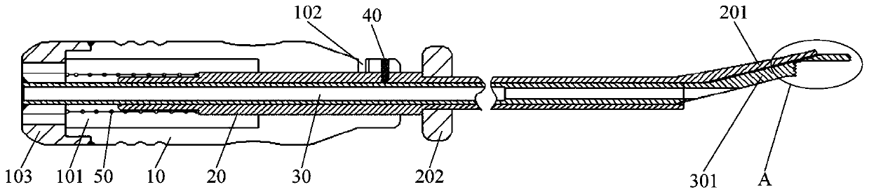
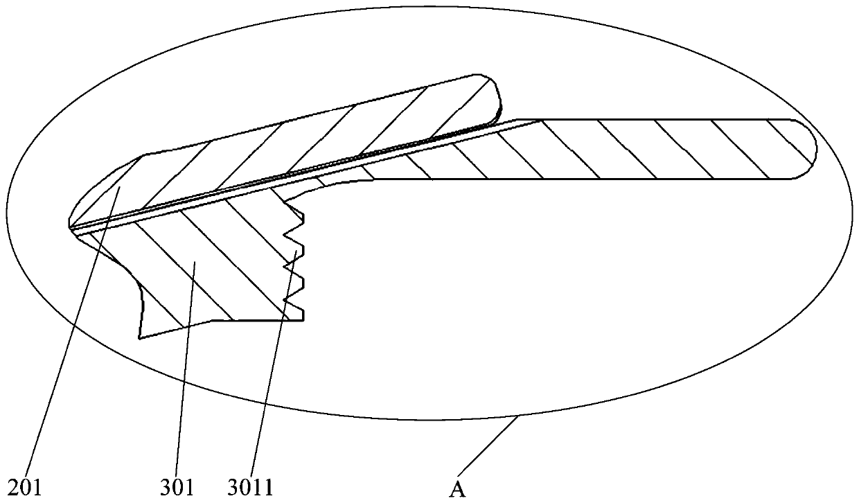
[0034] figure 1 Schematic diagram of the structure of the bone drill collimator provided by the embodiment of the present invention; figure 2 for figure 1 Partial enlarged view of A in the center.

[0035] Please refer to figure 1 with figure 2 . This embodiment provides a bone drill collimator, comprising: a gripping part 10 and a guide t...


PUM


Abstract

The invention provides a bone drill sighting device. The bone drill sighting device comprises a holding part and a guide pipe, a guide hole is formed in the holding part, the guide pipe is arranged inthe guide hole in a penetrating mode, and a first limiting part and a second limiting part are arranged at the front end, deviating from the holding part, of the guide pipe; first included angles areformed between the first limiting part and the axis of the guide pipe and between the second limiting part and the axis of the guide pipe, and a second included angle is formed between the first limiting part and the second limiting part; the first limiting part is used for abutting against the first position of the shoulder blade, and the second limiting part is used for abutting against the second position of the shoulder blade. During an operation, the first limiting part is propped against a first position on a shoulder blade; and the second limiting part abuts against the second positionon the shoulder blade, so that the axis of the guide pipe directly faces the preset position on the shoulder blade, the bone drill penetrates through the guide pipe to form a second mounting hole inthe shoulder blade, the position of the second mounting hole is accurate, the position of a bone block is easy to control, and the operation effect is good.

Description

technical field [0001] The invention relates to the technical field of medical instruments, in particular to a bone drill aimer. Background technique [0002] Recurrent shoulder dislocation refers to the failure to repair the damaged joint capsule and labrum in time after the first trauma, so that the patient's accidental movements in daily life lead to repeated dislocation of the shoulder joint; therefore, how to treat recurrent shoulder dislocation has become a research topic. hotspots. [0003] In the prior art, part of the bone fragment is often cut from the patient's coracoid process, and then the bone fragment is fixed on the scapula outside the labrum of the patient with the bone fragment fixing screw. The bone fragment can prevent the spherical articular cartilage from detaching from the labrum. This prevents shoulder dislocation. During the operation, part of the bone block is first cut off from the coracoid process of the patient, and the first installation hole ...

Claims


Application Information

Patent Timeline
IPC IPC(8): A61B17/17
CPCA61B17/1778A61B2017/564
Inventor 崔国庆程序罗浩
Owner PEKING UNIV THIRD HOSPITAL
Why Eureka
Try Eureka