
Friction stir welding track automatic perception and control method suitable for fillet joint

A technology of friction stir welding and fillet joints, which is applied to welding equipment, manufacturing tools, non-electric welding equipment, etc., can solve the problems of small structural parts, scratched welding plates, and small contact area, so as to improve welding production efficiency and reduce The possibility of scratching the welding plate, the effect of reducing the sliding friction force

Active Publication Date: 2020-08-07
NANJING UNIV OF SCI & TECH
View PDF6 Cites 4 Cited by
  • Summary
  • Abstract
  • Description
  • Claims
  • Application Information

AI Technical Summary

Problems solved by technology

Later, it was developed to sense the vertical height change of the butt weld by installing a roller in front of the stirring head, but this method cannot be used for the weld of the fillet joint
Robotic friction stir welding is to complete the welding of the weld seam by programming the motion trajectory of the robot, but it is difficult for the robot friction stir welding to complete a long weld seam, and the structural parts that can be welded are small, especially when welding thicker welding plates or hardness large welding plate
In addition, when welding fillet joints, the stirring head needs to make the inclined surface of the static shoulder fully fit on the surface of the welding plate, which requires a small contact area between the stirring head and the welding plate. The conventional static shoulder design is When the welding direction is slightly deviated, it will scratch the welding plate

Method used


Image

  • Friction stir welding track automatic perception and control method suitable for fillet joint
  • Friction stir welding track automatic perception and control method suitable for fillet joint

Examples


Embodiment Construction

[0034] Below in conjunction with accompanying drawing, the present invention will be further described

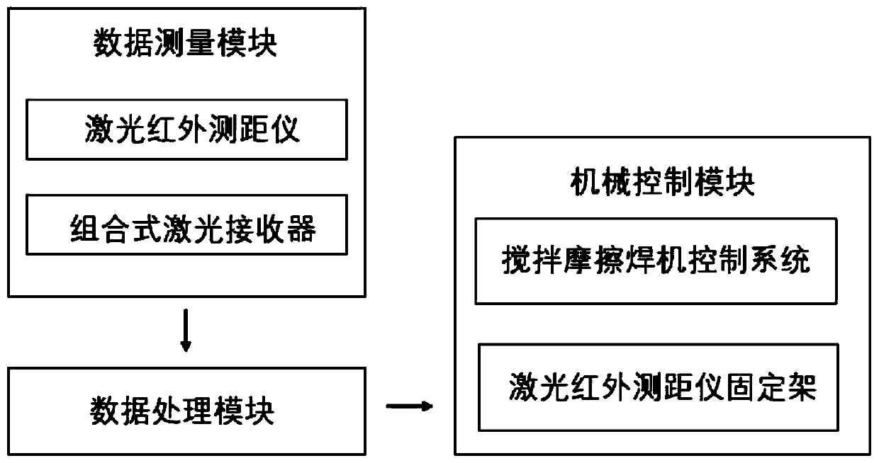
[0035] The method of the present invention utilizes as figure 1 The devices shown are:

[0036]The data measurement module includes a laser infrared range finder, a laser receiver and a fixing frame, the laser infrared range finder and the laser receiver are used to measure the position change of the welding plate in real time, and send information to the data processing module; The frame is used to clamp a laser infrared rangefinder and a laser receiver above the welding plate; the data processing module is used to receive the measurement distance sent by the data measurement module in real time, and then make it according to the input in advance The parameter and algorithm obtain the distance that the stirring head needs to move up and down, and send the information to the mechanical control module; the mechanical control module is used to control the downward pressure o...


PUM


Abstract

The invention provides a friction stir welding track automatic perception and control method suitable for a fillet joint. The method comprises the steps: firstly, a data measuring module measures andcalculates weld joint data in real time, a data processing module calculates stirring head adjusting data according to the measured data, finally an adjusting command of a stirring head is implementedthrough a mechanical control module, finally the fillet joint welding process does not need to be manually adjusted, as for linear right-angle welding or arc right-angle welding, the position of thestirring head can be automatically adjusted, and welding is completed. The friction stir welding fillet joint is automatically welded, a welding track is automatically adjusted, and the welding production efficiency is improved.

Description

technical field [0001] The invention relates to the field of automatic welding of friction stir welding and the field of design of a static shoulder stirring head, in particular to an automatic sensing and control method of a friction stir welding trajectory suitable for fillet joints. Background technique [0002] Production automation has always been the ultimate goal of continuous research and improvement of production equipment and production systems. As a new welding method, friction stir welding has attracted the attention of researchers at home and abroad. With the research on the structure of the stirring head and the welding process, it has been possible to weld Welds of various structures such as fillet joints, lap joints and spot welded joints. [0003] However, in the current welding equipment, the machine tool type friction stir welding machine is mainly used. Machine-tool friction stir welding machines are capable of welding longer welds, but there are still p...

Claims


Application Information

Patent Timeline
Patent Type & Authority Applications(China)
IPC IPC(8): B23K20/12B23K20/26
CPCB23K20/1245B23K20/26
Inventor 王克鸿孙智鸣闫燕燕孙晨薇汪海金鸣许雪宗宋正东
Owner NANJING UNIV OF SCI & TECH
Learn More