Machined part positioning mechanism for numerical control machining lathe

A technology of positioning mechanism and processing parts, applied in metal processing machinery parts, positioning devices, metal processing equipment and other directions, can solve the problems of reducing work economic benefits, reducing work efficiency, troublesome operation process, etc., to improve work economic benefits, improve Work efficiency and ensure the effect of processing quality

Active Publication Date: 2020-08-07
广东巡峰精密制造有限公司
View PDF8 Cites 9 Cited by
  • Summary
  • Abstract
  • Description
  • Claims
  • Application Information

AI Technical Summary

Problems solved by technology

[0003] For CNC lathes in the process of processing, the position of the workpiece needs to be positioned and fixed to facilitate the processing work. The positioning devices are all arranged on the rotating shaft on the equipment. When processing cylindrical workpieces, on the one hand, the prior art The positioning and fixing of the workpiece is more troublesome, the operation process is more troublesome, and the work efficiency is reduced. On the other hand, the positioning and fixing of the workpiece is not firm enough, which may cause position loosening and position deviation during the processing process, thereby affecting the processing quality. The setting causes the processing failure of the product, and then reduces the economic benefit of the work. For this reason, the present invention proposes a workpiece positioning mechanism used on a CNC machining lathe to solve the above problems

Method used


Image

  • Machined part positioning mechanism for numerical control machining lathe
  • Machined part positioning mechanism for numerical control machining lathe
  • Machined part positioning mechanism for numerical control machining lathe

Examples


Embodiment Construction

[0027] The technical solutions in the embodiments of the present invention will be clearly and completely described below. The embodiments of the present invention and all other embodiments obtained by persons of ordinary skill in the art without making creative efforts belong to the protection scope of the present invention.

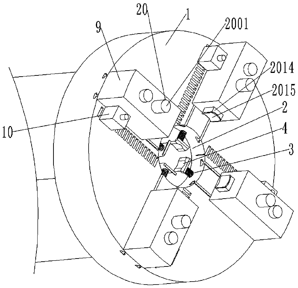
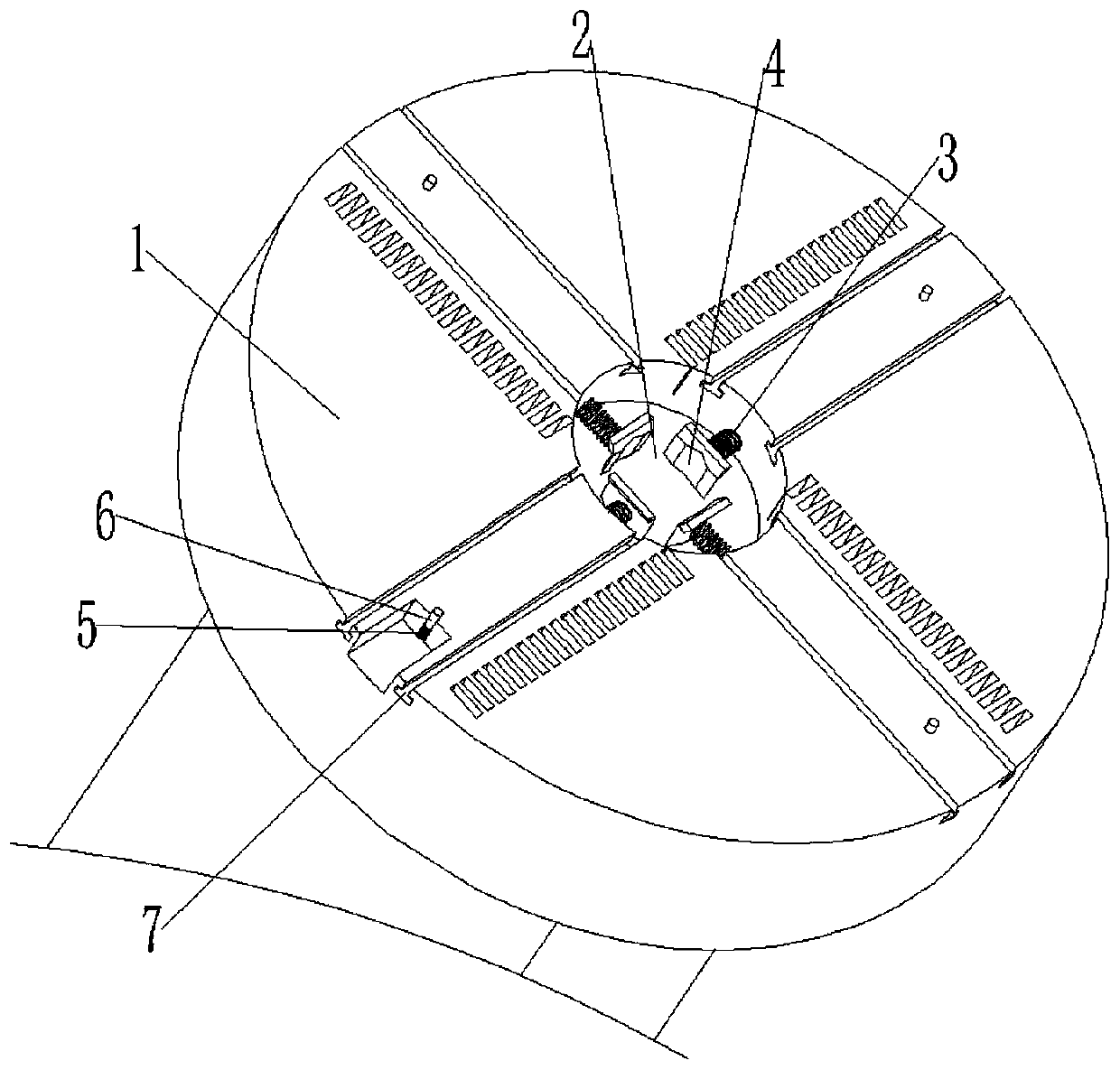
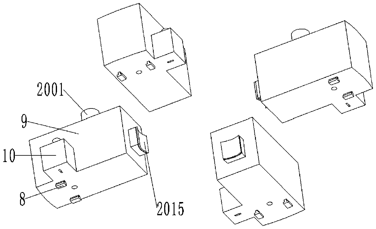
[0028] see figure see Figure 1 to Figure 7 , the present invention provides a technical solution: a workpiece positioning mechanism used on a CNC machining lathe, including a turntable 1, a placement groove 2, a sliding body 9 and a positioning and clamping structure 20;

[0029] The center of the circle on one side of the turntable 1 is provided with a placement groove 2, and the inner wall of the placement groove 2 is integrally formed and symmetrically provided with a first connecting spring 3, and the other end of the first connecting spring 3 is integrally formed and connected with an arc-shaped plate 4, which is symmetrical in the turntable 1. A...


PUM


Abstract

The invention discloses a machined part positioning mechanism for a numerical control machining lathe. The machined part positioning mechanism comprises a rotary disc, a containing groove, a sliding body and a positioning and clamping structure; the containing groove is formed in the circle center position of one side of the rotary disc, first connecting springs are symmetrically arranged on the inner side wall of the containing groove in an integrally-formed mode, and an arc-shaped plate is arranged at the other ends of the first connecting springs in an integrally-formed and connected mode.According to the machined part positioning mechanism for the numerical control machining lathe, through the arrangement of the containing groove, the first connecting springs, the arc-shaped plate andthe sliding body, good positioning function is achieved on a machined workpiece, rapidly positioning and fixing the workpiece can be carried out, convenience is brought to workers, the working efficiency is improved; and through the arranged positioning and clamping structure, the firmness of workpiece positioning and fixing can be improved, looseness is not likely to be generated in the machining work, the fact that normal work is carried out is guaranteed, the machining quality is guaranteed, and then the work economic benefits are improved.

Description

technical field [0001] The invention relates to the technical field of numerical control processing equipment, in particular to a processing piece positioning mechanism used on a numerical control processing lathe. Background technique [0002] CNC lathe processing is a high-precision, high-efficiency automatic machine tool that uses digital information to control the displacement of parts and tools; An effective way to achieve high-efficiency and automated processing, CNC lathe processing is also a high-tech processing method for precision hardware parts; various types of materials can be processed, including 316, 304 stainless steel, carbon steel, alloy steel, alloy aluminum, zinc alloy , titanium alloy, copper, iron, plastic, acrylic, POM, UHWM and other raw materials can be processed into square and round parts with complex structures. Other ancillary equipment cooperate to complete the work of workpiece processing. [0003] For CNC lathes in the process of processing,...

Claims


Application Information

Patent Timeline
Patent Type & Authority Applications(China)
IPC IPC(8): B23Q3/00B23Q3/18
CPCB23Q3/00B23Q3/18
Inventor 蒋佳
Owner 广东巡峰精密制造有限公司
Why Eureka
Try Eureka