Woodworking machine
A technology of woodworking machines and racks, which is applied in the direction of wood processing equipment, manufacturing tools, forming/shaping machines, etc., can solve the problem of low detection accuracy of tool holders, and achieve the effect of regular layout, high detection accuracy, and easy layout
- Summary
- Abstract
- Description
- Claims
- Application Information
AI Technical Summary
Problems solved by technology
Method used
Image

Examples
Embodiment 1
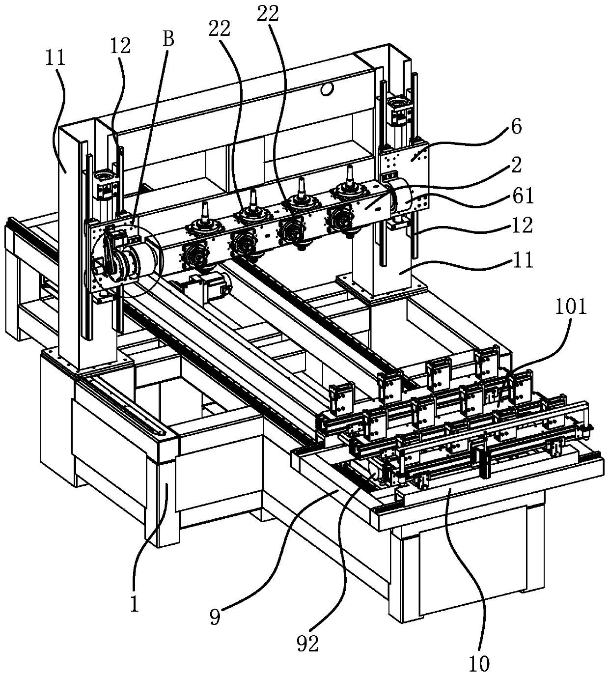
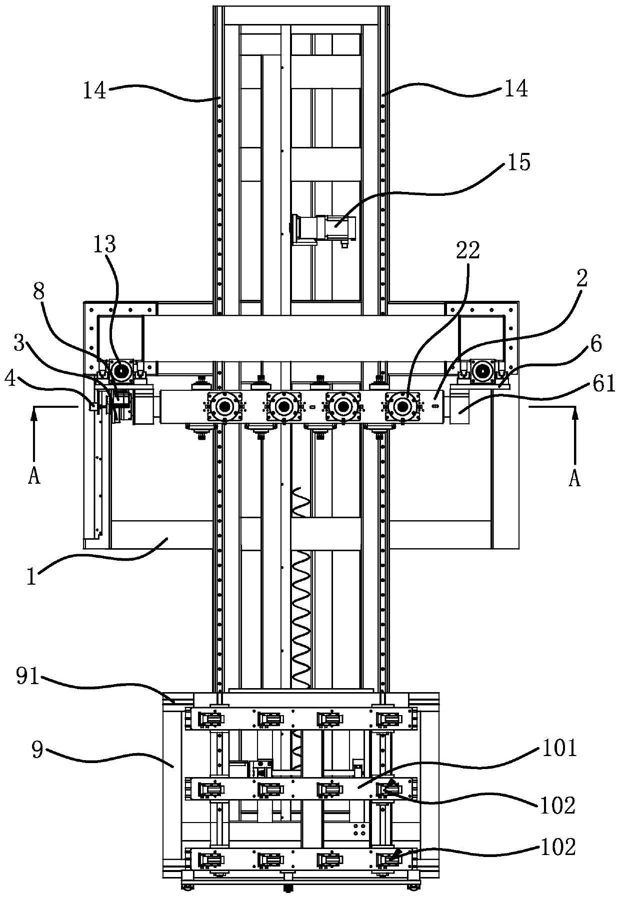
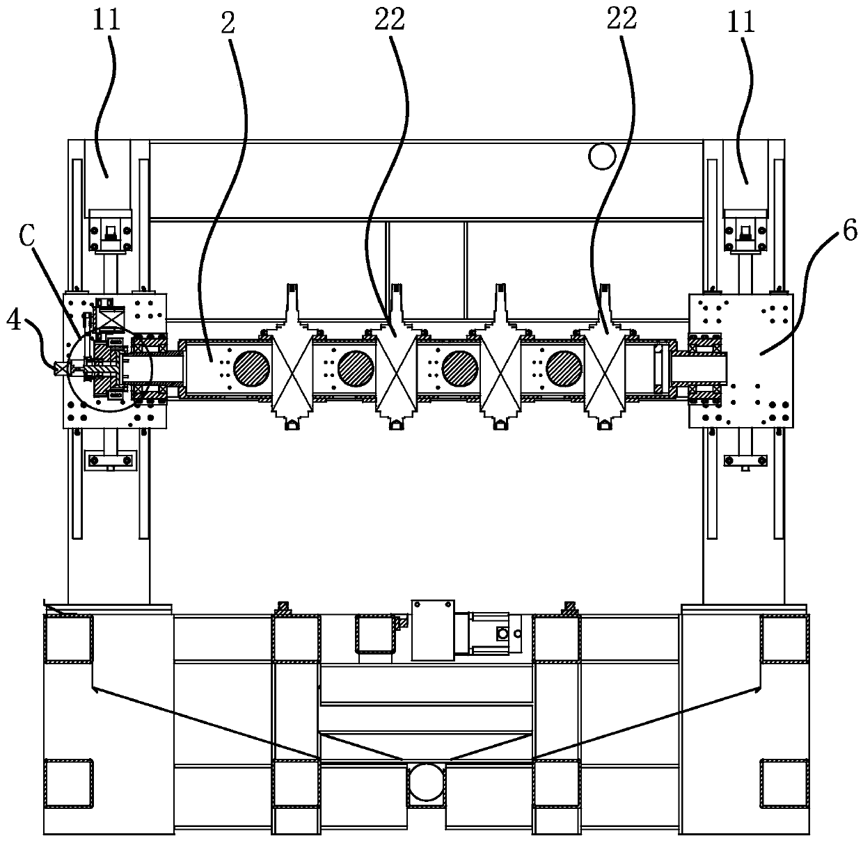
[0033] Such as figure 1 , figure 2 , image 3 As shown, the woodworking machine includes a frame 1, a processing platform 101, a moving assembly and a tool rack 2. The frame 1 includes two vertical columns 11 arranged on both lateral sides, and the moving assembly includes two vertical carriages 6. The two vertical The carriage 6 is slidably connected to the two uprights 11 along the vertical direction respectively. The tool holder 2 is in the shape of a strip square tube. On the tool holder 2, several processing motors 22 are fixed. The several processing motors 22 are arranged horizontally, and some processing motors The knives on the 22 extend out of different sides of the tool holder 2 respectively, and supports 61 are fixed on the sides of the two vertical carriages 6, the tool holder 2 is arranged horizontally, and the two ends of the tool holder 2 are respectively welded and fixed with a circular tubular The mounting portion 21 of the tool holder 2 is connected to th...
Embodiment 2
[0038] The structure of this woodworking machine is basically the same as that of Embodiment 1, the difference is that the input end of the encoder 4 is columnar, and the input end of the encoder 4 passes through the avoidance hole 31 along the transverse direction and directly connects with the connecting part 71 on the connecting sleeve 7 Phase solid connection.
Embodiment 3
[0040] The structure of this woodworking machine is basically the same as that of Embodiment 1, the difference is that Image 6 As shown, the connection sleeve 7 has a disc-shaped connection portion 71 inside, the connection portion 71 is integrally formed with the connection sleeve 7 and arranged coaxially, the center of the connection portion 71 is provided with a connection hole 711, and the connection hole 711 faces one end of the tool holder 2 There is a limit groove 712 in the circumferential direction of the hole, the end of the intermediate shaft 5 is inserted into the connecting hole 711 and is firmly connected with the connecting part 71, the end of the intermediate shaft 5 passes through the connecting hole 711, and the intermediate shaft 5 passes through the The over-end has a limit plate 51, and the limit plate 51 is positioned in the limit groove 712, so that the intermediate shaft 5 and the connecting sleeve 7 are arranged coaxially.
PUM
 Abstract
Description
Claims
Application Information
 - R&D Engineer
- R&D Manager
- IP Professional
- Industry Leading Data Capabilities
- Powerful AI technology
- Patent DNA Extraction
Browse by: Latest US Patents, China's latest patents, Technical Efficacy Thesaurus, Application Domain, Technology Topic.
© 2024 PatSnap. All rights reserved.Legal|Privacy policy|Modern Slavery Act Transparency Statement|Sitemap