Novel spinning roller for spinner

A technology of textile machines and rolls, applied in the direction of winding strips, static electricity, electrical components, etc., can solve problems such as easy wrinkles, high safety hazards in textile workshops, troublesome fabric winding, etc., and achieve the effect of reducing wrinkles.

Inactive Publication Date: 2020-08-07
万海龙
View PDF11 Cites 0 Cited by
  • Summary
  • Abstract
  • Description
  • Claims
  • Application Information

AI Technical Summary

Problems solved by technology

[0003] Most of the textile fabrics are now made of chemical fiber materials. During the production process of chemical fiber materials, they need to be leveled by multiple rollers. The cloth is prone to static electricity when it rubs against the surface of the rollers of the textile machine. Due to The mutual attraction of electric charges will make the winding of the fabric very troublesome, prone to wrinkles and other problems, and if the static electricity is not dealt with in time, it will pose a great safety hazard to the flammable textile workshop

Method used


Image

  • Novel spinning roller for spinner
  • Novel spinning roller for spinner

Examples


Embodiment Construction

[0016] The following will clearly and completely describe the technical solutions in the embodiments of the present invention with reference to the accompanying drawings in the embodiments of the present invention. Obviously, the described embodiments are only some, not all, embodiments of the present invention.

[0017] In describing the present invention, it should be understood that the terms "upper", "lower", "front", "rear", "left", "right", "top", "bottom", "inner", " The orientation or positional relationship indicated by "outside", etc. is based on the orientation or positional relationship shown in the drawings, and is only for the convenience of describing the present invention and simplifying the description, rather than indicating or implying that the referred device or element must have a specific orientation, so as to Specific orientation configurations and operations, therefore, are not to be construed as limitations on the invention.

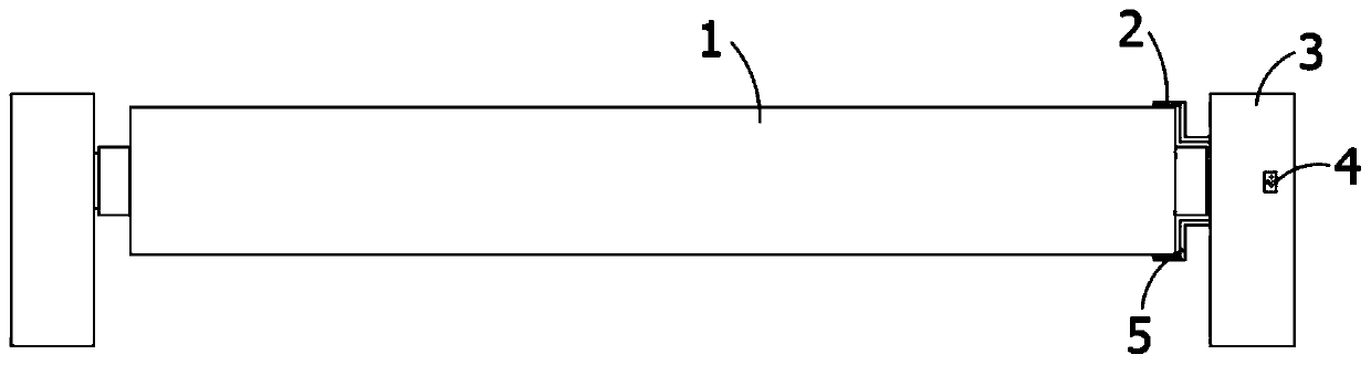
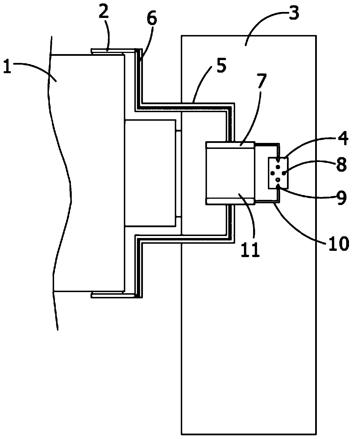
[0018] refer to Figure ...


PUM


Abstract

The invention discloses a novel spinning roller for spinner. The novel spinning roller comprises a roller rotatably installed between two supporting columns, a capacitor cavity and a discharge grooveare formed in one of the supporting columns, the capacitor cavity is a closed space, a plurality of holes are formed in one side of the discharge groove, electrodes are symmetrically and fixedly installed on the upper and lower side walls of the capacitor cavity, connecting shafts are correspondingly and fixedly connected to one sides of the two electrodes, the two connecting shafts penetrate through the supporting columns, guide wires are installed in the connecting shafts, and brush blades are fixedly connected to the ends, away from the electrodes, of the connecting shafts. According to thenovel spinning roller, the situation that the static electricity can guide and difference of binding ability of different materials to electrons are utilized, through the guide, the generated staticelectricity is collected, the potential difference is effectively formed between the two electrodes, thus the generated static electricity is collected, the influence of the static electricity generated by friction on the winding effect of textile cloth is avoided, and the wrinkle problem caused by the charge effect is solved.

Description

technical field [0001] The invention relates to the technical field of textile equipment, in particular to a novel textile roll for a textile machine. Background technique [0002] The machinery for producing chemical fibers includes a variety of chemical machinery, which is now considered an extension of textile machinery. The processes required to process different fibers such as cotton, hemp, silk, and wool into textiles are different, and some are completely different. Therefore, it is necessary to There are also various types of machines. Textile machinery is the production means and material basis of the textile industry. Its technical level, quality and manufacturing cost are directly related to the development of the textile industry. [0003] Most of the textile fabrics are now made of chemical fiber materials. During the production process of chemical fiber materials, they need to be leveled by multiple rollers. The cloth is prone to static electricity when it rubs...

Claims


Application Information

Patent Timeline
Patent Type & Authority Applications(China)
IPC IPC(8): B65H27/00H05F3/04
CPCB65H27/00B65H2301/5133B65H2404/19H05F3/04
Inventor 万海龙
Owner 万海龙
Why Eureka
Try Eureka