An automatic winding machine for discharge coil

A technology of discharge coil and winding machine, which is applied in the direction of coil, coil manufacturing, circuit, etc., can solve the problems of high labor intensity, poor coil quality stability, and high defective rate, so as to improve the winding quality, achieve tightness, and shorten the manufacturing cycle. Effect

Active Publication Date: 2017-07-18
SHAANXI DAGONG XUHANG ELECTROMAGNETIC TECH CO LTD
View PDF1 Cites 0 Cited by
  • Summary
  • Abstract
  • Description
  • Claims
  • Application Information

AI Technical Summary

Problems solved by technology

Although the manufacturing method of the discharge coil can complete the production of the discharge coil, it cannot accurately control the winding speed of the coil, and the labor intensity is high, and it is easily disturbed by human factors; the quality stability of the coil is poor, and the defective rate is high, so it is difficult to ensure the high efficiency of the coil. and long life

Method used


Image

  • An automatic winding machine for discharge coil
  • An automatic winding machine for discharge coil

Examples


Embodiment

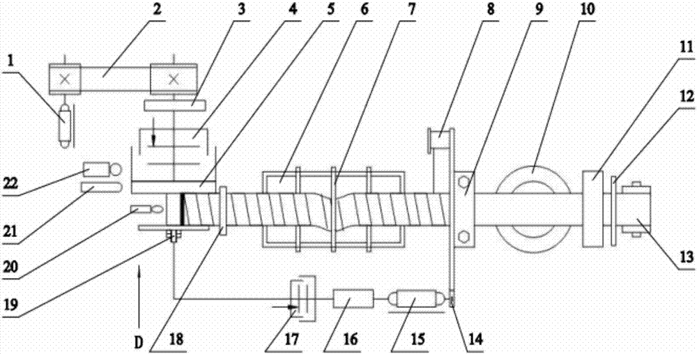
[0037] In this embodiment, the outer diameter of the coil is φ100mm, the thickness of the copper strip is 0.5mm, and the length is 6760mm. Glass fiber cloth with a width of 35mm and a thickness of 0.2mm is laminated on the copper strip, and the thickness of the wrapped copper strip is close to 1mm. The inner diameter of the coil shell is φ90. The diameter of the copper core is φ18, the copper strip can be wound 41 times, and the winding time is 3 minutes.

[0038] Such as figure 1 As shown in the figure, one end of the copper strip is welded to the joint, and the other end is welded to the copper core. After grinding, cleaning, and calibration, it is rolled into a disc and installed on the winding machine. Wrap the baked and cleaned glass fiber cloth and install it on the tape reel 14, then install the copper core on the main shaft of the winding machine, pour the adjusted glue into the dipping tank 6, and make the glass fiber cloth wrapped The copper strip can be fully dipp...


PUM


Abstract

The invention discloses an automatic winding machine used for a discharge coil. The automatic winding machine is a winding device used for a discharge coil of a core component of an electromagnetic forming device in the fields of aviation, aerospace and automobiles; the instantaneous feed speed of a copper belt can be synchronously fed back to a servomotor of a winding plate, and glass fiber cloth is controlled to be uniformly wound around the surface of the copper belt, so that the winding quality of the discharge coil is improved. A driving mechanism provides power for the whole system. A clamping mechanism ensures that the copper belt is in a straight and tensioned state during a winding process, so that uniform feeding of the copper belt is facilitated. A glue scraping and coating assembly is used for finishing impregnation glue-coating of the copper belt and the glass fiber cloth, as well as scraping of residual insulated resin glue on the surfaces of the copper belt and the glass fiber cloth. A rotational speed control mechanism realizes synchronous adjustment of the rotational speed of the belt winding plate. An electromagnetic clutch enables a coil winding mould to drive a main shaft to rotate and stop for preventing the rotation and stop of the motor from inertially influencing a coil winding effect. A counting sensor and a limiting switch control a coil winding number and a coil winding outer diameter to ensure coil winding consistency; the service life of the discharge coil is prolonged.

Description

technical field [0001] The invention relates to the technical field of process equipment structure design and manufacture, in particular to an automatic winding machine for discharge coils. Background technique [0002] Electromagnetic forming equipment includes electromagnetic riveting equipment, stress wave installation equipment and electromagnetic forming machines. Electromagnetic forming equipment has been widely used in aerospace and home appliance manufacturing fields. The discharge coil is the key component of the electromagnetic riveting forming equipment. One of the key technologies in the winding process of the discharge coil is the control of the feeding speed of the copper strip and the winding speed of the insulating cloth. As the outer diameter of the coil increases, its winding speed also needs to be changed accordingly. [0003] Invention patent 200810232458.4 discloses "a manufacturing method of electromagnetic riveting gun discharge coil". The manufactu...

Claims


Application Information

Patent Timeline
Patent Type & Authority Patents(China)
IPC IPC(8): H01F41/061H01F41/082H01F41/12H01F5/00
CPCH01F5/00H01F41/122
Inventor 曹增强杨晓娜仇继伟陈昶张帆乔婷婷
Owner SHAANXI DAGONG XUHANG ELECTROMAGNETIC TECH CO LTD
Why Eureka
Try Eureka