Accelerating and pressurizing system

A technology of booster system and switching valve, which is applied in fluid pressure converter, fluid pressure actuating device, servo motor, etc., can solve the problem of high cost, and achieve fast no-load operation speed, low cost, and increase in size. The effect of maximum output force

Pending Publication Date: 2020-08-07
山河智能特种装备有限公司
View PDF0 Cites 2 Cited by
  • Summary
  • Abstract
  • Description
  • Claims
  • Application Information

AI Technical Summary

Problems solved by technology

[0003] The current solution is to select the pressure level of the corresponding hydraulic system and the displacement of the main pump according to the needs of the large-bore high-pressure cylinder to meet the high-pressure and large-flow output of the hydraulic cylinder, and then realize

Method used


Image

  • Accelerating and pressurizing system
  • Accelerating and pressurizing system
  • Accelerating and pressurizing system

Examples


Embodiment 1

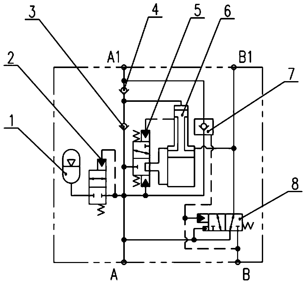
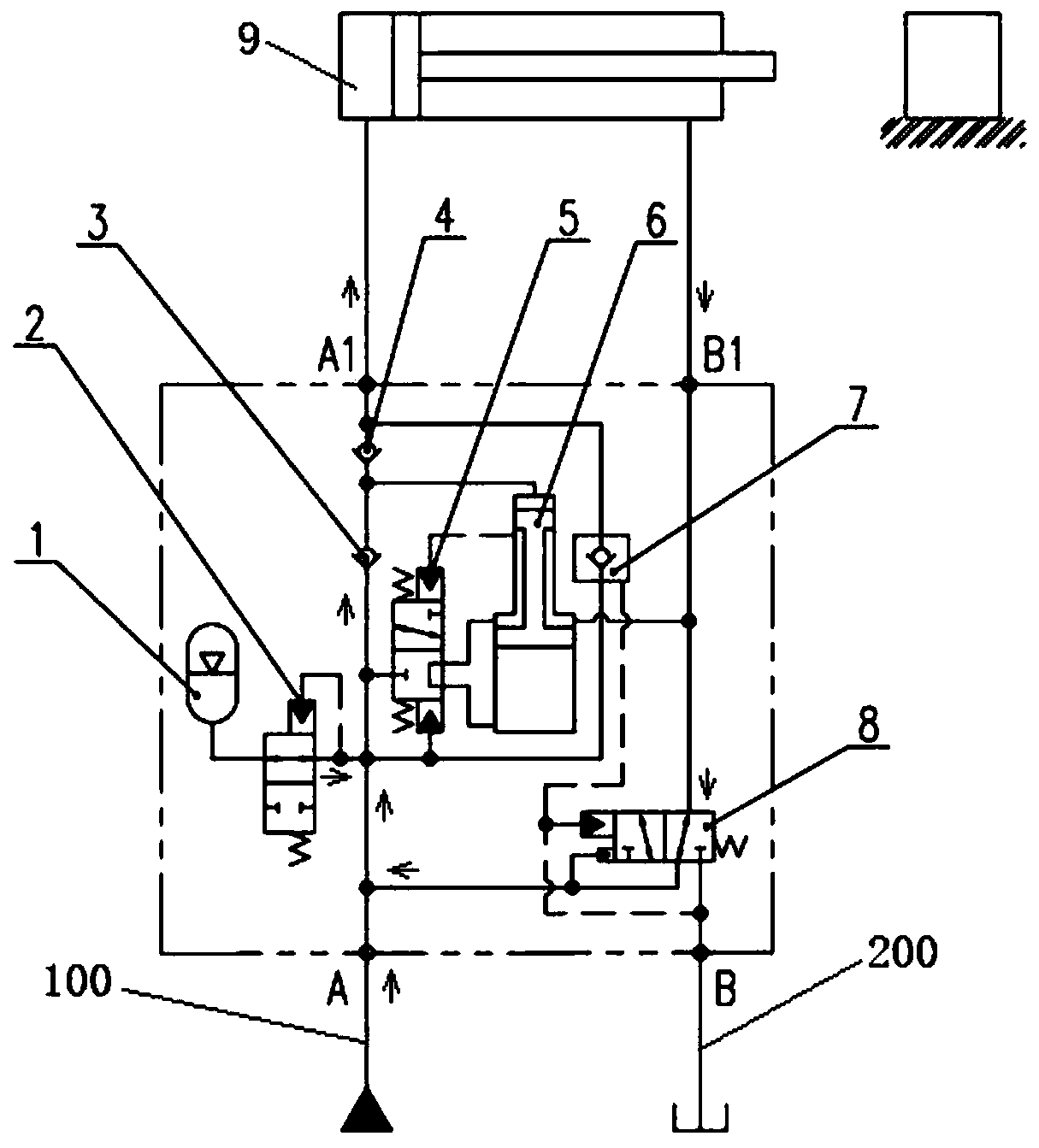
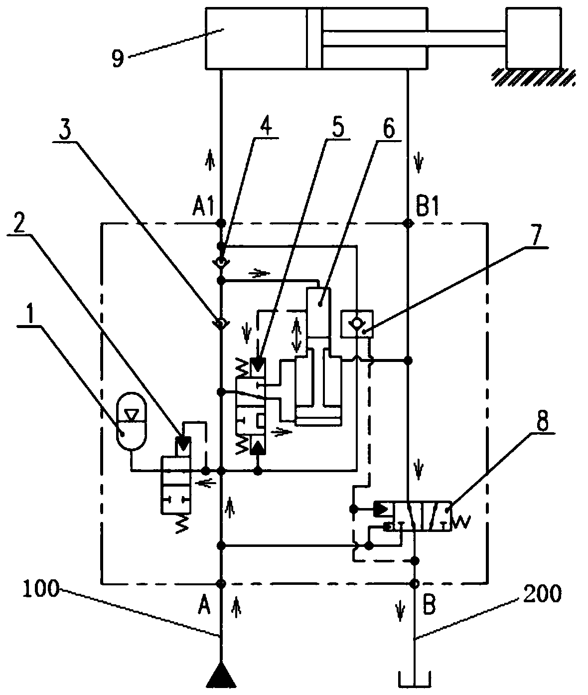
[0030] see figure 1 , the acceleration and supercharging system in the illustration is a specific embodiment of the present invention, specifically including an accumulator 1, a first switching valve 2, a first one-way valve 3, a second one-way valve 4, and a second switching valve 5. Double-acting oil cylinder 6, hydraulic control check valve 7 and third switching valve 8. combine figure 2 and image 3 As shown, the acceleration and supercharging system of this embodiment realizes the purpose of no-load acceleration and load supercharging during the process of performing work of the oil cylinder 9 . The acceleration and supercharging system of this embodiment is arranged on the inlet and outlet oil passage of the executive cylinder 9, wherein the large chamber and the small chamber of the executive cylinder 9 are respectively connected with the A1 port and the B1 port of the acceleration and supercharging system, and the A port of the accelerating and supercharging system ...

Embodiment 2

[0044] see Figure 5 , this embodiment is yet another specific implementation of the acceleration and supercharging system of the present invention, and the difference from Embodiment 1 is: the first switching valve 2, the second switching valve 5 and the third switching valve in this embodiment 8 all use electronically controlled reversing valves, which can be triggered and switched by pressure sensors or position sensors set on the oil circuit.

[0045] For example, both the first switching valve 2 and the third switching valve 8 are feedback-controlled by the pressure sensor arranged on the working oil inlet circuit 100, and the action of the second switching valve 5 is fed back according to the position sensor that detects the piston movement of the double-acting cylinder 6 control.

[0046] When the executive oil cylinder 9 stretches out with no load, the pumped pressure oil enters the working oil inlet circuit 100 from the A port. As long as the internal pressure of the...


PUM


Abstract

The invention discloses an accelerating and pressurizing system. The accelerating and pressurizing system comprises a second switching valve, a double-acting oil cylinder and a third switching valve which are arranged on an oil inlet and outlet path of an execution oil cylinder; a piston with a large end and a small end is arranged in the double-acting oil cylinder, a large cavity and a small cavity of the double-acting oil cylinder correspond to the large end and the small end of the piston respectively, the double-acting oil cylinder is connected with branches through the large cavity and the small cavity and arranged on a working oil inlet way of the execution oil cylinder in parallel, and the second switching valve is arranged on the branch connected with the large cavity of the double-acting oil cylinder; and the third switching valve is arranged on a working oil return path of the execution oil cylinder and is used for switching and connecting an oil return port of the executionoil cylinder between the working oil return path and the working oil inlet path. According to the accelerating and pressurizing system, on the premise that the discharge capacity and the pressure level of a main pump do not need to be changed, the accelerating and pressurizing system is additionally arranged on the working oil way of the execution oil cylinder, so that the no-load running speed ofthe execution oil cylinder is increased, the maximum output force of the oil cylinder load is increased, and the execution oil cylinder can stretch out rapidly or with large thrust.

Description

technical field [0001] The invention belongs to hydraulic control technology, and in particular relates to an acceleration and boosting system of a hydraulic oil cylinder. Background technique [0002] In construction machinery, construction machinery and factory automation equipment driven by hydraulic pressure, the hydraulic cylinder is the main actuator. Due to the actual work requirements and design lightweight considerations, the hydraulic cylinder requires speed to move to the contact load during the no-load process, and the flow rate needs to be increased. After the load, it is necessary to increase the pressure to do work on the load. The flow and pressure required by the hydraulic cylinder are often inconsistent. Therefore, there are cases where a single or a few groups of actions need to output a large thrust and use a large-bore high-pressure cylinder. [0003] The current solution is to select the pressure level of the corresponding hydraulic system and the displ...

Claims


Application Information

Patent Timeline
IPC IPC(8): F15B3/00F15B1/02F15B11/08F15B13/042
CPCF15B1/024F15B3/00F15B11/08F15B13/042F15B2211/212F15B2211/50
Inventor 王金钢王玲彭建新
Owner 山河智能特种装备有限公司
Why Eureka
Try Eureka