Pump-driven two-phase fluid loop evaporator

A fluid circuit and evaporator technology, used in the field of pump-driven two-phase fluid circuit evaporators, can solve the problems of easy accumulation of liquid, large contact thermal resistance, large thermal resistance, etc. Effect of Evaporative Heat Transfer Coefficient

Active Publication Date: 2020-08-07
SHANGHAI SATELLITE ENG INST
View PDF6 Cites 5 Cited by
  • Summary
  • Abstract
  • Description
  • Claims
  • Application Information

AI Technical Summary

Problems solved by technology

[0003] However, the existing capillary pumps generally adopt hydrophilic capillary core material and reverse capillary core structure. On the one hand, the direction of liquid flow in the reverse capillary core is opposite to the direction of heat flow, and the gas-liquid interface continues to flow when the heat flow is large. Backward, the distance from the shell continues to expand, resulting in greater thermal resistance; on the other hand, the capillary core and the shell are often made separately and compressed by interference fit, and the contact thermal resistance between the two is relatively large; In addition, the reverse capillary structure makes the cross-sectional area of ​​the steam channel in the evaporator very small, and it is easy to accumulate liquid after filling, transportation, different orientations or certain working conditions. When the evaporation channel is filled with liquid, the heat sink must be To achieve a large degree of superheat, the formation of nucleate boiling in the steam channel, let the steam drive out most of the liquid to achieve stable evaporation heat transfer
These three factors make the start-up performance of the evaporative heat sink and the evaporation coefficient during stable operation still have a large room for improvement.

Method used


Image

  • Pump-driven two-phase fluid loop evaporator
  • Pump-driven two-phase fluid loop evaporator
  • Pump-driven two-phase fluid loop evaporator

Examples


Embodiment Construction

[0036] The present invention will be described in detail below in conjunction with specific embodiments. The following examples will help those skilled in the art to further understand the present invention, but do not limit the present invention in any form. It should be noted that those skilled in the art can make several changes and improvements without departing from the concept of the present invention. These all belong to the protection scope of the present invention.

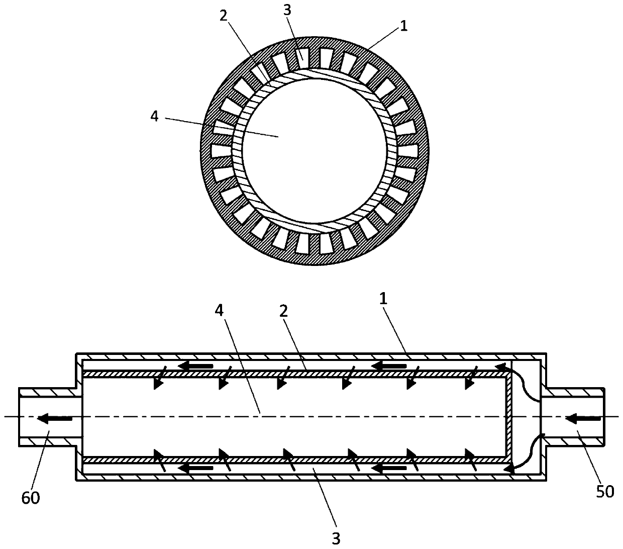
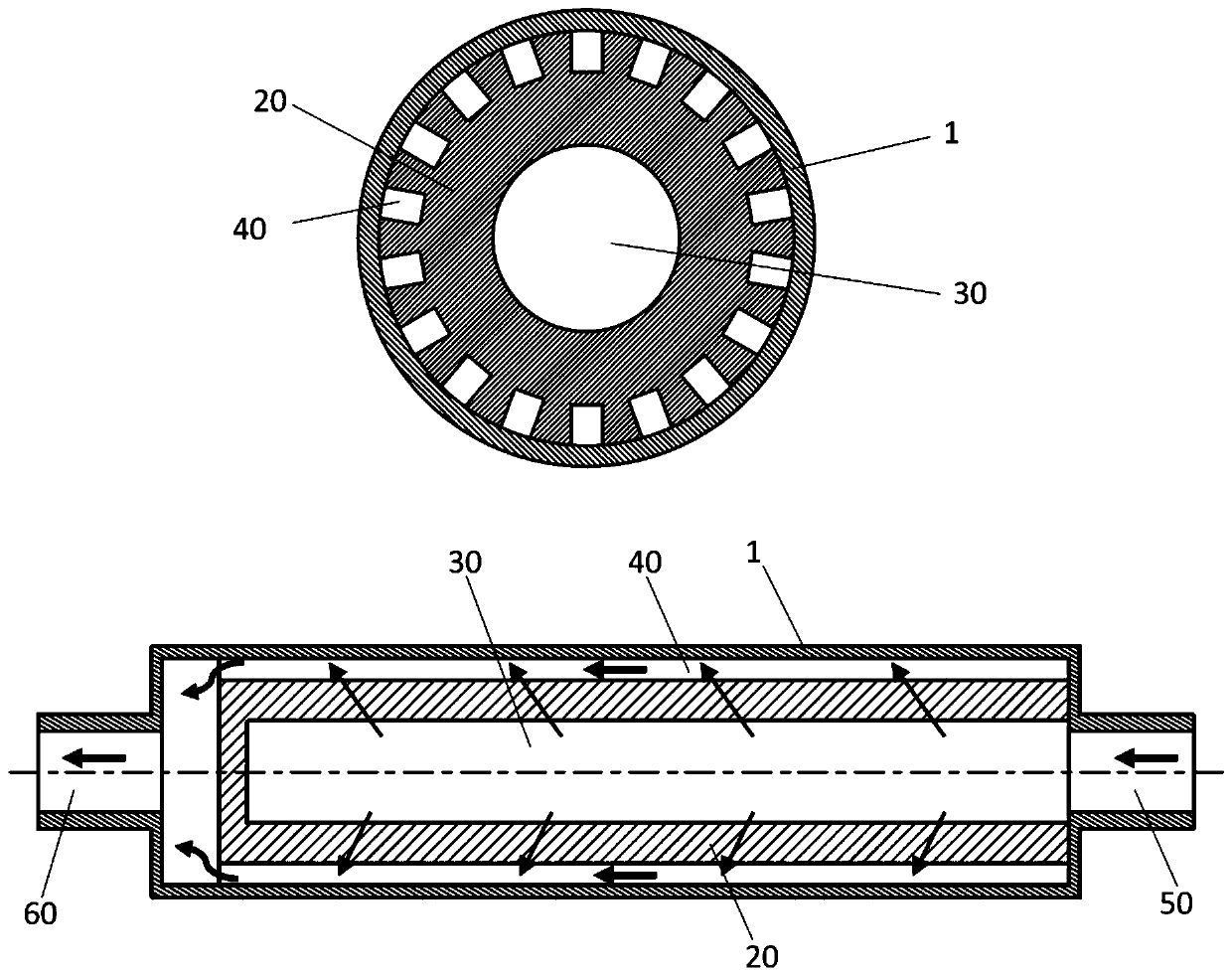
[0037] Such as figure 1 , Figure 3 to Figure 6 As shown, a pump-driven two-phase fluid circuit evaporator is provided according to the present invention. For a cylindrical evaporator, its structure includes: an evaporator shell 1, a hydrophobic wick 2, an axial liquid channel 3 and an axial steam channel 4; the hydrophobic wick 2 is mounted on the evaporator shell 1; the axial liquid channel 3 is arranged between the evaporator shell 1 and the hydrophobic capillary wick 2; the axial steam main channe...


PUM


Abstract

The invention provides a pump-driven two-phase fluid loop evaporator. The pump-driven two-phase fluid loop evaporator comprises an evaporator shell 1, a hydrophobic capillary core 2, axial liquid channels 3 and an axial steam main channel 4; the hydrophobic capillary core 2 is mounted inside the evaporator shell 1; the plurality of axial liquid channels 3 are arranged between the evaporator shell1 and the hydrophobic capillary core 2; and the axial steam main channel 4 is arranged inside the hydrophobic capillary core 2. For a two-phase fluid loop driven by a capillary pump, a hydrophobic porous material is used for covering the surface of the open type tiny channel of the evaporator, so that liquid cannot occupy the space of the steam main channel due to condensation under the influenceof various orientations or gravity, meanwhile, steam bubbles possibly existing in the liquid channels can smoothly overflow out of the channels, smooth starting of the evaporator is facilitated, the superheat degree during starting is reduced, and the heat exchange coefficient in the evaporation process is increased.

Description

technical field [0001] The invention relates to the technical field of heat transfer elements, in particular to a pump-driven two-phase fluid circuit evaporator. Background technique [0002] Many current two-phase fluid circuit designs use evaporative heat sinks, such as loop heat pipes, capillary suction loops, mechanical pump-assisted loop heat pipes or capillary suction loops, or purely mechanical pump-driven, gas-liquid separation two-phase fluids loop etc. A traditional gravity-assisted multi-evaporator two-phase fluid circuit device disclosed in patent document CN107529365B includes a capillary evaporator, a vapor pipeline, a condenser pipeline, a liquid pipeline, and a liquid reservoir, and it also includes a steam Confluence, inverted U-shaped pipe fittings, loop valves, liquid input pipelines, liquid splitters, and 3 to 12 capillary evaporators, which are evenly arranged on the heat source, and the condenser pipeline is connected in series with the liquid receiver...

Claims


Application Information

Patent Timeline
Patent Type & Authority Applications(China)
IPC IPC(8): F28D15/04
CPCF28D15/043
Inventor 李志松姜建飞牟旭娜申军烽许忠林
Owner SHANGHAI SATELLITE ENG INST
Why Eureka
Try Eureka