Laser lighting device

A laser illumination and laser technology, which is applied in the direction of using optical devices, measuring devices, and optical devices to transmit sensing components, etc., can solve the problems of difficult to increase optical output power, small diffusion angle, uneven irradiation distribution of annular light spots, etc. Achieve the effect of avoiding uneven distribution of radiation

Active Publication Date: 2020-08-07
常州酷童智能科技有限公司
View PDF8 Cites 1 Cited by
  • Summary
  • Abstract
  • Description
  • Claims
  • Application Information

AI Technical Summary

Problems solved by technology

[0003] In order to overcome the above-mentioned technical problems, the purpose of the present invention is to provide a laser lighting device. The present invention emits monochromatic light through the laser, and the gradient refractive index lens reduces the diffusion angle of the outgoing light of the laser, and focuses the light beam to Smaller than the diameter of the fiber entrance, the fiber transmits the light energy and maintains a small diffusion angle to the convex lens. The convex lens reduces the light diffusion angle at the output end of the fiber and corrects the beam to be collimated. The focusing lens barrel passes through Rotation can move the convex lens along the optical axis, adjust the distance between the lens and the fiber port, and then adjust the light diffusion angle at the output end of the fiber. The light beam reaches the conical reflector, and the conical reflector directs the light beam to Diffusion in the plane to form a ring-shaped spot, this device can generate a ring-shaped spot, and solve the problem that the irradiance distribution of the ring-shaped spot is not uniform, and the light output power is difficult to increase

Method used


Image

  • Laser lighting device

Examples


Embodiment Construction

[0015] The following will clearly and completely describe the technical solutions in the embodiments of the present invention with reference to the accompanying drawings in the embodiments of the present invention. Obviously, the described embodiments are only some, not all, embodiments of the present invention. Based on the embodiments of the present invention, all other embodiments obtained by persons of ordinary skill in the art without creative efforts fall within the protection scope of the present invention.

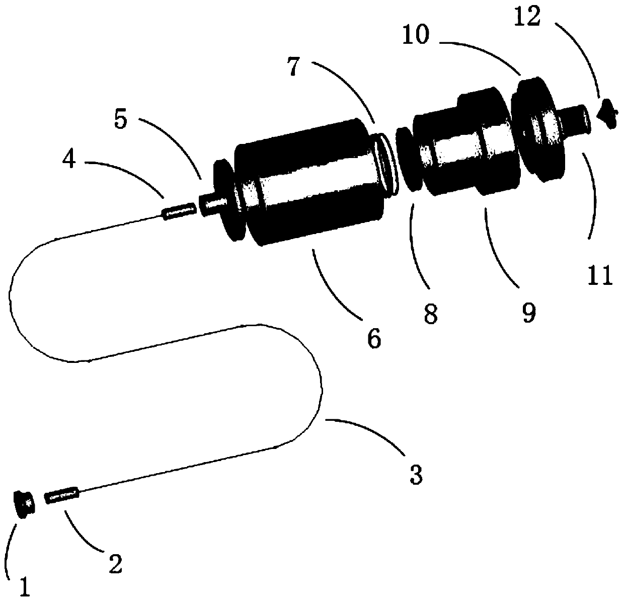
[0016] see figure 1 As shown, a laser illumination device includes a laser 1, a gradient variable refractive index lens 2, an optical fiber 3, an optical fiber plug 4, an optical fiber flange 5, a main lens barrel 6 and an optical assembly, and one side of the laser 1 is installed with a gradient A variable refractive index lens 2, the laser 1 is used as a light source to generate monochromatic light, the laser 1 can be an edge emitting laser or a vertical cavity s...


PUM


Abstract

The invention discloses a laser lighting device. The device comprises a laser, a gradient variable refractive index lens, an optical fiber, an optical fiber plug, an optical fiber flange, a main lensbarrel and an optical assembly, the gradient variable refractive index lens is mounted on one side of the laser; the other side of the gradient variable refractive index lens is connected with the optical fiber plug through the optical fiber; the optical fiber plug is inserted into the optical fiber flange; the other end of the optical fiber flange is connected with the optical assembly, the optical assembly is installed in the main lens barrel, the optical assembly comprises a focusing lens barrel, a convex lens is fixedly installed in the focusing lens barrel through a lens ring, and a conical lens installation base is installed at the end, away from the main lens barrel, of the focusing lens barrel; annular light spots can be generated, and the problems that the irradiation distributionof the annular light spots is not uniform, and the light output power is difficult to improve are solved.

Description

technical field [0001] The invention relates to the technical field of lighting devices, in particular to a laser lighting device. Background technique [0002] In vision measurement systems, lighting components are important components. In the measurement system based on structured light, a high-quality linear light source is required. The main technical requirements are: small diffusion angle, usually not greater than 1mrad; high light intensity, the light radiation received by the irradiated surface The light intensity is greater than 1mW / cm2. In circular cross-section geometric measurement applications, a light source that produces an annular spot is also required. The existing technical solutions mainly include the following types: one is to use multiple linear light sources for splicing processing, which has the advantage that the optical system is relatively simple, and it is easy to use a laser light source with high output power. High-precision mechanical structu...

Claims


Application Information

Patent Timeline
Patent Type & Authority Applications(China)
IPC IPC(8): G01D5/26G01D5/353G01B11/00G01N21/01G02B27/09G02B27/30
CPCG01D5/268G01D5/353G01B11/00G01N21/01G02B27/0927G02B27/0938G02B27/30G01N2201/06113G01N2201/063G01N2021/0112G01N2201/084G01N2201/08
Inventor 刘晓亮徐顺东戴小燕
Owner 常州酷童智能科技有限公司
Why Eureka
Try Eureka