Laying system for laying optical cables along low-friction pipeline and optical cable laying method thereof

A technology for optical cables and pipes, which is applied in the field of tools for floor equipment installation, which can solve problems such as inconvenient carrying, laborious manual pipe penetration, and limited routing length, etc., and achieve the effects of saving charging, shortening the construction period, and improving construction efficiency

Pending Publication Date: 2020-08-07
远东通讯有限公司
View PDF0 Cites 1 Cited by
  • Summary
  • Abstract
  • Description
  • Claims
  • Application Information

AI Technical Summary

Problems solved by technology

This wiring method has the following disadvantages: 1. The location of the fiber distribution box in the corridor is relatively narrow, and it is not easy to operate manually; 2. The length of the pipeline from the fiber distribution box in the corridor to the user is sometimes long, and it is laborious and time-consuming to thread the pipe manually ;3. When the optical cable is threaded manually, it is greatly affected by the operator's proficiency in the pipe threading and the force of the threading force. For example, the pipe is blocked, the pipe is crushed, etc.
[0006] 2. The fiber optic cable is laid by air blowing from the fiber distribution box in the corridor to introduce the optical cable into the information panel of the user's home. This wiring method also has the following disadvantages: 1. The optical cable is laid by air blowing - air blowing micro tube + air blowing micro cable +Air blowing equipment, this method is suitable for long-distance field operations, and requires the use of air blowers, air compressors, generators and other machinery and equipment. The equipment is relatively large and inconvenient to carry. It is not conducive to the deployment of optical cables in buildings; 2. The cable type of air-blown micro-cables is generally round and the outer diameter is small. Blowing laying; 3. The use of air blowing laying of optical cables has high requirements for the skills of operators, and special training is required before they can work.
[0007] For surface-mounted line card wiring, its disadvantages are: irregular operation, unsafe, unsightly, and surface-mounted line cards will damage the existing indoor decoration; for preset PVC line pipes, its disadvantages are: non-full routing pipes, PVC The tubes are discontinuous, easy to block, the length of the route is limited, and the optical cable is easily damaged by manual pulling

Method used


Image

  • Laying system for laying optical cables along low-friction pipeline and optical cable laying method thereof
  • Laying system for laying optical cables along low-friction pipeline and optical cable laying method thereof
  • Laying system for laying optical cables along low-friction pipeline and optical cable laying method thereof

Examples


Embodiment

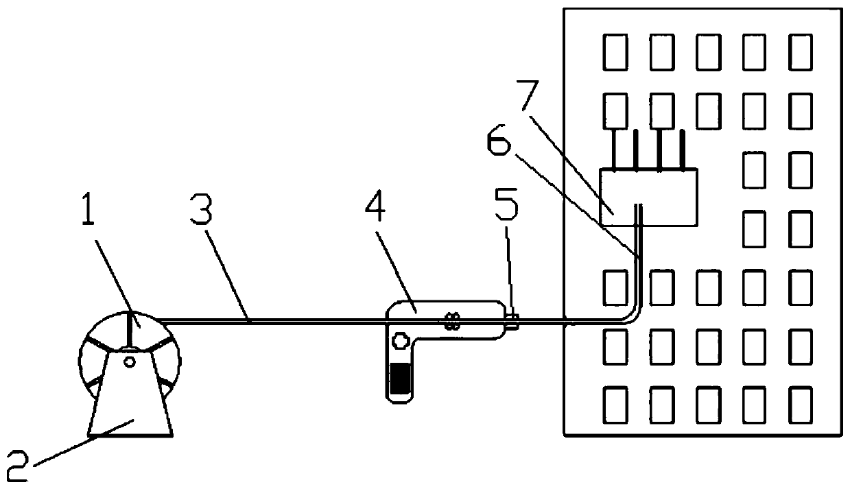
[0034] Embodiment: A deployment system for laying optical cables along a low-friction pipeline and a method for laying optical cables. In this embodiment, the friction coefficient of the inner wall of the low-friction pipeline is less than 0.25, and the inner wall of the wiring pipeline 6 is coated with a silicon core. The inner diameter size is preferably 5mm / 3.5mm, the maximum outer diameter of which is no more than 8mm, the optical cable adopts a small-sized structure with an outer diameter of less than 2.7mm, and the ratio of the outer diameter of the optical cable to the inner diameter of the wiring duct 6 is no greater than 0.85.

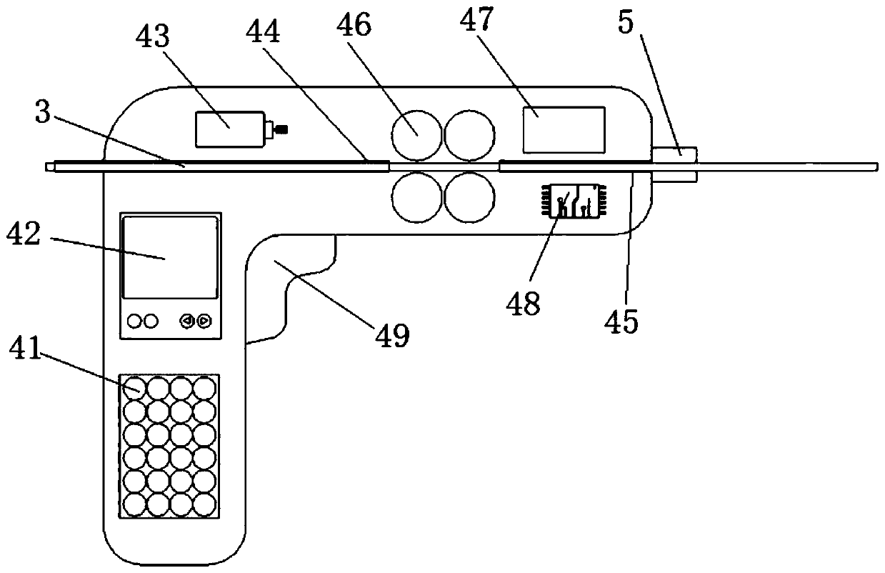
[0035] as attached figure 1 As shown, the deployment system includes an optical cable reel 1, an optical cable pay-off device 2 and an electric push device 4; an optical cable 3 is wound on the optical cable reel 1, and the optical cable reel 1 is installed on the optical cable pay-off device 2, and the optical cable pay-off device 2. A simple...


PUM


Abstract

The invention discloses a laying system for laying an optical cable along a low-friction pipeline and an optical cable laying method thereof. The laying system comprises an optical cable reel, an optical cable pay-off device and an electric pushing device, wherein an optical cable is wound on the optical cable reel, the optical cable reel is installed on the optical cable pay-off device, the electric pushing device is located between the wiring pipeline and the optical cable pay-off device, and the optical cable is conveyed into the wiring pipeline through the electric pushing device. The electric pushing device comprises a power device, a pushing mechanism and a torque sensor; the power device provides pushing power for the pushing mechanism, the pushing mechanism is a conveying double-row roller, the conveying double-row roller clamps an optical cable and drives the optical cable to move, a torque sensor is installed on the conveying double-row roller, and the torque sensor monitorsthe pushing force of the optical cable. The optical cable reel and the electric pushing device are used, so an optical cable enters a wiring pipeline, and the laying of the optical cable is achieved.

Description

technical field [0001] The invention relates to a tool for installing floor equipment, in particular to a laying system for laying optical cables along a low-friction pipeline and a method for laying optical cables. Background technique [0002] The application scenarios of optical cables extend from the intercity backbone network—the metropolitan area network—access network—to the user side, forming an orderly and complex information transmission network; with the rapid development of Internet technology, information transmission technology With iterative updates, various applications developed based on Internet technology appear and deeply affect people's work and life. In recent years, the country has accelerated the construction of network information transmission infrastructure and people's demand for network bandwidth has increased. As the carrier of information transmission, optical cables have been deployed in every corner of the city, and optical cable wiring has al...

Claims


Application Information

Patent Timeline
Patent Type & Authority Applications(China)
IPC IPC(8): G02B6/50G02B6/54
CPCG02B6/50G02B6/54
Inventor 万冰段宏峰袁健李鑫鑫吴煜张瑞
Owner 远东通讯有限公司
Why Eureka
Try Eureka