Long-life sewage treatment equipment

A technology for sewage treatment equipment and longevity, applied in the direction of filtration separation, separation method, mobile filter element filter, etc., can solve the problems of poor filtering effect of waste debris, stagnant sewage, inconvenient storage and treatment of defective materials, etc., and achieve improvement Space utilization efficiency, increased contact area, convenient cooling and storage

Inactive Publication Date: 2020-08-11
黄广仙
View PDF0 Cites 0 Cited by
  • Summary
  • Abstract
  • Description
  • Claims
  • Application Information

AI Technical Summary

Problems solved by technology

[0003] However, if a simple filter screen is installed inside the drainage channel, the filtering effect on the waste debris is poor, and the filter screen is easy to be blocked, and the waste debris is bonded to the filter screen, which is not easy to clean, and it is necessary to squeeze the waste into the injection molding machine during the start-up process. Throw the defective materials out into the water tank to cool down to avoid sticking between multiple pieces of defective materials. Use a water tank with universal wheels to cool the defective materials. The water tank is not easy to carry inside the workshop, and The sewage inside the water tank does not flow. When there are many defective materials, the temperature of the water source inside the water tank rises, and the cooling effect on the defective materials is poor, and it is not convenient to store and process the defective materials

Method used


Image

  • Long-life sewage treatment equipment
  • Long-life sewage treatment equipment
  • Long-life sewage treatment equipment

Examples


Embodiment Construction

[0028] In order to make the technical means, creative features, goals and effects achieved by the present invention easy to understand, the present invention will be further described below in conjunction with specific embodiments.

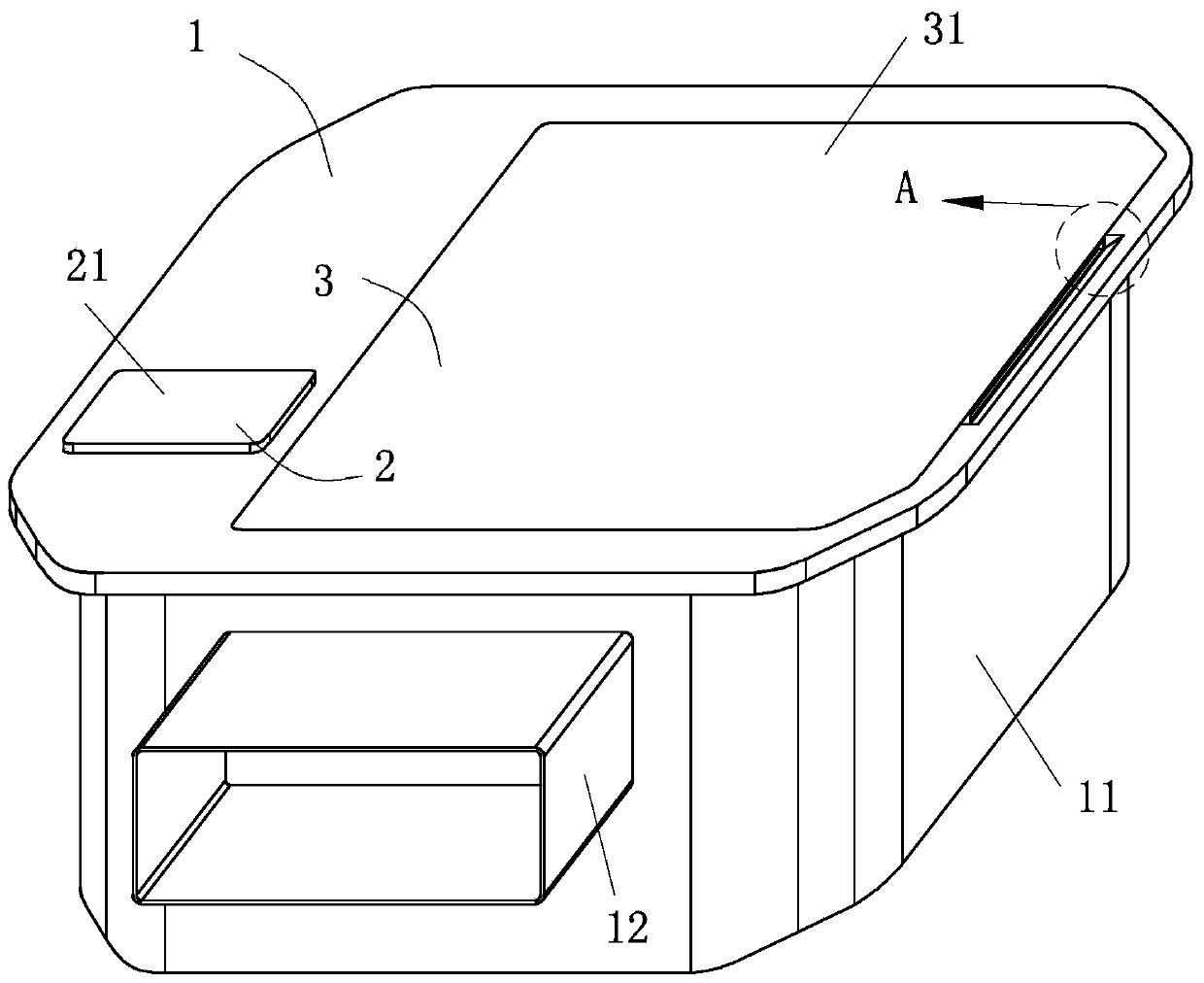
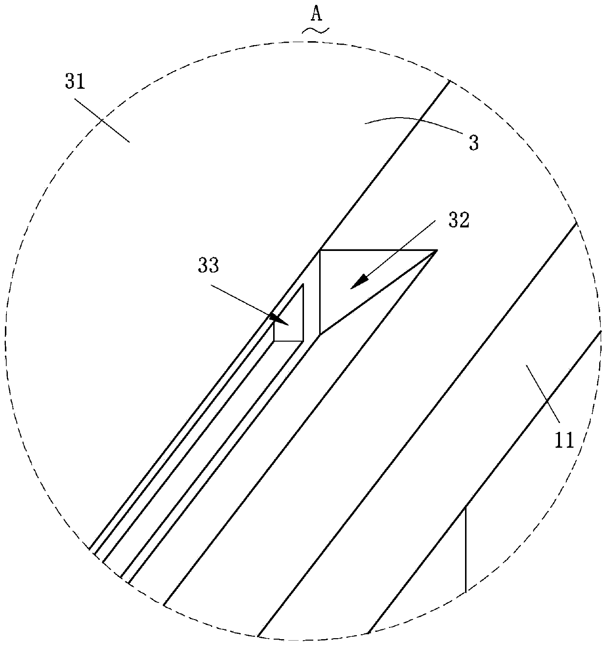
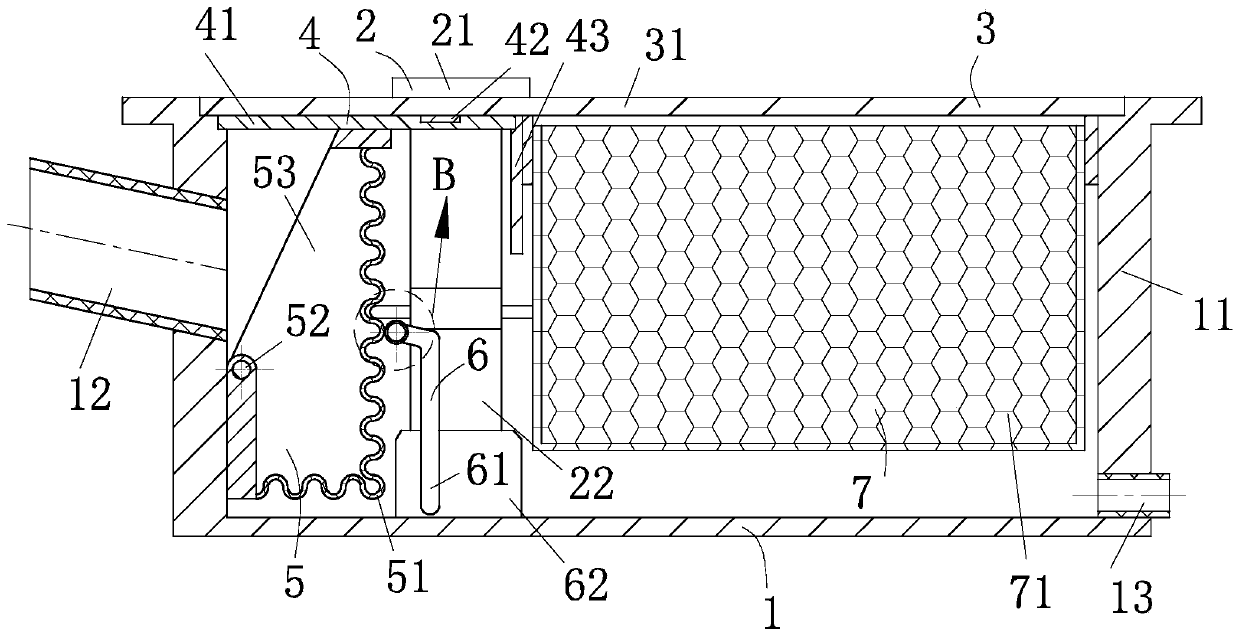
[0029] Such as Figure 1-Figure 8 As shown, a high-life sewage treatment equipment according to the present invention includes a storage structure 1, a driving structure 2, a sealing structure 3, a separation structure 4, a first filtering structure 5, a pressurizing structure 6 and a second filtering structure 7; The interior of the storage structure 1 for storing water sources is provided with the first filter structure 5 for filtering waste and the second filter structure 7 for cooling defective lumpy materials, and the first Both the filtering structure 5 and the second filtering structure 7 are rotatably connected to the storage structure 1; The separation structure 4 is separated; the inside of the storage structure 1 is provided with the d...


PUM

PropertyMeasurementUnit
angleaaaaaaaaaa

Abstract

The invention relates to the field of sewage treatment, in particular to long-life sewage treatment equipment which comprises a storage structure, a driving structure, a sealing structure, a separation structure, a first filtering structure, a pressurizing structure and a second filtering structure. The driving structure used for driving the first filtering structure and the second filtering structure to shake is arranged in the storage structure, so that the driving structure drives the first filtering structure and the second filtering structure to shake conveniently, the treatment effect ofsweeps in sewage is better, and meanwhile, the treatment effect of startup waste is better. The driving structure is connected to the pressurizing structure for backwashing the first filtering structure, and the pressurizing structure is arranged in the storage structure, therefore, the pressurizing structure is driven by the driving structure to backwash the first filtering structure conveniently, the anti-blocking performance of the first filtering structure is improved, meanwhile, the water flow speed is increased, and the cooling effect of water flow on the startup waste is better.

Description

technical field [0001] The invention relates to the field of sewage treatment, in particular to a long-life sewage treatment equipment. Background technique [0002] Sewage treatment refers to the process of purifying sewage to meet the water quality requirements for discharge into a certain water body or reuse; sewage treatment is widely used in construction, agriculture, transportation, energy, petrochemical, environmental protection, urban landscape, medical treatment, In various fields such as catering, for example, a drainage channel is set at the bottom of the cooling water tank in the PE winding pipe production workshop, so that the water source discharged from the water tank and the sewage splashed on the ground flow back to the cooling tower through the drainage channel, and then transported to the cooling water tank The internal recycling uses the filter screen to filter the sewage inside the opened drainage channel, effectively preventing the material and its cut ...

Claims


Application Information

Patent Timeline
Patent Type & Authority Applications(China)
IPC IPC(8): B01D33/41B01D33/50B01D33/76B01D33/80
CPCB01D33/41B01D33/503B01D33/76B01D33/801B01D33/803
Inventor 黄广仙
Owner 黄广仙
Why Eureka
Try Eureka