A sewage tank sludge cleaning device

A technology for cleaning device and sewage tank, which is applied in the field of sewage tank sludge cleaning device and sewage tank sludge cleaning device, which can solve the problems of more mixing, turbid sewage, inconvenient sludge storage and treatment, etc., and achieves alleviation The effect of water turbidity, reducing water flow disturbance, and facilitating subsequent storage and treatment

Active Publication Date: 2022-01-11
徐州新南湖科技有限公司
View PDF2 Cites 0 Cited by
  • Summary
  • Abstract
  • Description
  • Claims
  • Application Information

AI Technical Summary

Problems solved by technology

[0004] Notification number CN210230907U discloses a kind of efficient and convenient cleaning device for sewage pool, including box body, driving device, housing, dredging device, box door, heat dissipation port, filter screen plate and installation block, and the device is provided with helical blades directly on the Stirring the sludge at the bottom will easily make the purified sewage turbid again, and the discharged sludge is mixed with more water, which is not convenient for sludge storage and treatment

Method used


Image

  • A sewage tank sludge cleaning device
  • A sewage tank sludge cleaning device
  • A sewage tank sludge cleaning device

Examples


Embodiment 1

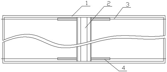
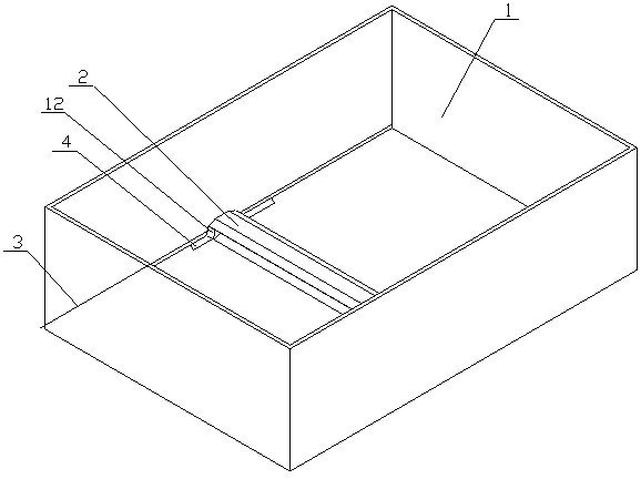
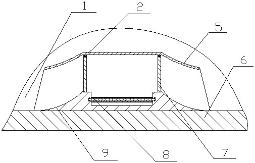
[0022] A sewage pool sludge cleaning apparatus is achieved by a sewage pool cleaning device of the present invention, by a main casing (2), traction rope (3), water scaffold (4), and a guide plate ( 5), mud plate (7), conveyor belt (8), shovel plate (9), mud groove (10), drive motor (11), motor mount (12), and belt conveyor rollers (14), The bottom of the main housing (2) is connected to both ends of the shovel (9), and the main housing (2) is an open structure, and the two mud plate (7) respectively. Placed on both sides of the main housing (2), the mud plate (7) is coupled to the top of the hinge shaft and the main housing (2), which is capable of rotating relative to the main housing (2) The two guides (5) are fixed to the top of the main casing (2), the guiding plate (5) being an arcuate plate, the shovel plate (9) has two Curved sputum surface, two of the arc-shaped spatches surfaces, respectively, respectively, respectively, and the arc-shaped female face is consistent with ...

Embodiment 2

[0030]The difference from the first embodiment is that the bottom of the shovel plate (9) is opened, and a plurality of ball (13) grooves are opened on the top of the rolling recess, the ball (13). The groove is a curved groove, the ball (13) slot is arranged in an array, and the ball (13) groove has a rotatable ball (13); when used, the ball (13) rotates during the movement of the device. Change the sliding friction into rolling friction, can reduce the friction between the bottom of the shovel plate (9) and the bottom of the pool;

[0031] The designer of the mud groove (10) is designed, and the mud bag can be sandwiched, and the sludge can be directly falling into the mud bag from the slot slot (10), facilitating the treatment of sludge;

[0032] The shovel plate (9) has two curved sputum surfaces, and the two arcules (5) respectively, respectively, and the curved sputum surface and the mud. The arc-shaped design of the plate is more advantageous to bring the sludge of the sewa...


PUM


Abstract

The invention discloses a sewage pool sludge cleaning device which discloses a sewage pool sludge which can be moved and cleaned at the bottom of the pool by a traction rope pulling device, which can reduce water flow disturbance, is suitable for sewage pools of different sizes, and does not occupy the external space of the sewage pool. The cleaning device is characterized in that the bottoms at both ends of the main casing are respectively connected with the two ends of the dredging plate, the two sides of the main casing are open structures, and the two mud inlet plates are respectively placed on the two sides of the main casing. On the side, the mud inlet plate is connected to the top of the main casing through a hinge shaft, the mud inlet plate can rotate relative to the main casing, the two deflectors are fixed on the top of both sides of the main casing, the guide The flow plate is an arc-shaped plate, and two arc-shaped mud-guiding surfaces are placed on the scraper plate, and the two arc-shaped mud-guiding surfaces are respectively opposite to the two flow-guiding plates, and the arc-shaped mud-guiding surfaces are connected to the two guiding plates. The concave direction of the arc of the mud plate is consistent, and there is a mud inlet groove in the middle of the top of the mud scraper, and the mud inlet groove runs through both ends of the mud scraper.

Description

Technical field [0001] A sewage pool sludge cleaning apparatus relates to a device for sewage pool sludge cleaning, belonging to the field of sewage equipment. It is particularly related to a sewage pool of water flow through the traction rope pulling device to reduce water flow, and suitable for different sizes of sewage pool, and does not occupy a sewage pool sludge cleaning device of the outer space of the sewage pool. Background technique [0002] When the sewage is purified in the sewage pool, it will form sludge at the bottom of the sewage pool. When the sludge accumulation is much more affected, it is necessary to clean it. When cleaning, it is generally pulled into the pool in the pool. Then, the underwater work, which makes the suspension of sewage purification, and the artificial cleaning is also very expensive. The existing device for cleaning the sludge of the sewage pool, by providing the segment plate structure to separate the upper clarified liquid to the bottom sl...

Claims


Application Information

Patent Timeline
Patent Type & Authority Patents(China)
IPC IPC(8): B08B9/087C02F1/00
CPCB08B9/087C02F1/00C02F2303/14
Inventor 不公告发明人
Owner 徐州新南湖科技有限公司
Why Eureka
Try Eureka