
Longitudinal seam welding protection structure, barrel longitudinal seam welding device and corresponding welding method

A technology of longitudinal seam welding and protective structure, which is applied in the direction of auxiliary equipment, welding equipment, welding equipment, etc., to achieve the effect of optimizing the protection effect and introducing the effect of gas consumption

Active Publication Date: 2020-08-11
CHANGZHOU BORI ELECTRIC POWER AUTOMATION EQUIP
View PDF5 Cites 8 Cited by
  • Summary
  • Abstract
  • Description
  • Claims
  • Application Information

AI Technical Summary

Problems solved by technology

[0009] The first purpose of the present invention is to provide a longitudinal seam welding protection structure to solve the technical problem of optimizing the welding effect on the longitudinal seam of the cylinder
[0010] The second object of the present invention is to provide a cylinder longitudinal seam welding device to solve the technical problem of optimizing the welding effect on the cylinder longitudinal seam
[0011] The third object of the present invention is to provide a method for welding the longitudinal seam of the cylinder to solve the technical problem of optimizing the welding effect of the longitudinal seam of the cylinder

Method used


Image

  • Longitudinal seam welding protection structure, barrel longitudinal seam welding device and corresponding welding method
  • Longitudinal seam welding protection structure, barrel longitudinal seam welding device and corresponding welding method
  • Longitudinal seam welding protection structure, barrel longitudinal seam welding device and corresponding welding method

Examples


Embodiment 1

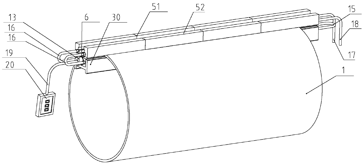
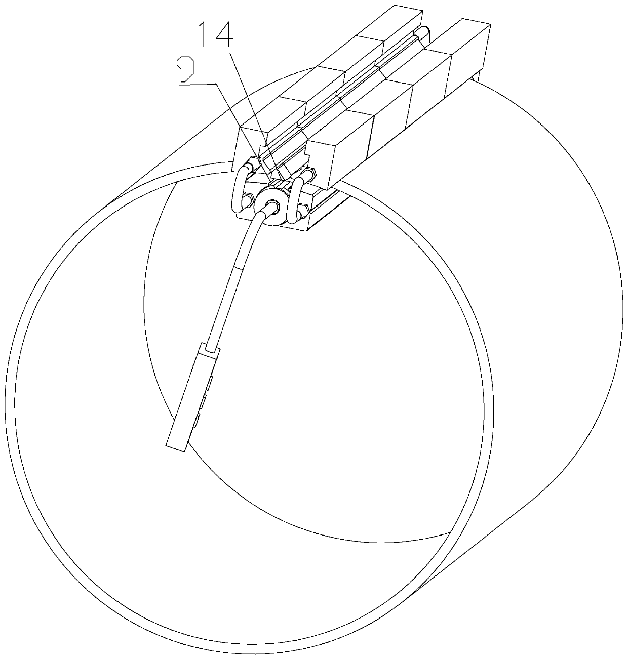
[0057] see Figure 1 to Figure 12 As shown, this embodiment provides a seam welding protection structure, including: a weld outer protection component and a weld inner protection component. The weld outer protection component here is located on the outside of the cylinder 1 during the welding process, while the welding inner protection component is located on the inside of the cylinder 1 during the welding process. , that is, the protective effect on the long longitudinal seam 2 of the cylinder body 1 during the welding process is jointly formed by the outer protective component of the weld and the inner protective component of the weld.

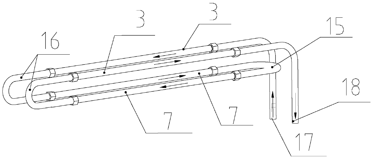
[0058] In detail, firstly, the weld outer protection assembly includes a pair of outer cooling pads adapted to abut against the cylinder body 1 on both sides of the longitudinal seam 2 from the outside of the cylinder body 1, and a pair of outer cooling pads along the length direction of the outer cooling pads. A pair of external cooling pi...

Embodiment 2

[0072] see Figure 1 to Figure 12As shown, on the basis of the longitudinal seam 2 welding protection structure in embodiment 1, this embodiment provides a cylinder longitudinal seam welding device, including: a cylinder supporting mechanism, a longitudinal seam 2 welding mechanism and the longitudinal seam welding mechanism of embodiment 1. Seam 2 welded protective structure. The cylinder support mechanism includes a support bracket 26 suitable for supporting the cylinder 1 from the bottom of the cylinder 1, and a base 27 fixedly connected with the bottom of the support bracket 26; The welding torch 28 for welding the longitudinal seam 2 and the mechanical arm 29 connected with the welding torch 28 to drive the welding torch 28 to move.

[0073] Considering the adequacy of effectively ensuring the contact between the protection component inside the weld of the longitudinal seam 2 welding protection structure and the outer wall and inner wall of the cylinder 1, the welding de...

Embodiment 3

[0078] On the basis of the cylinder longitudinal seam welding device in embodiment 2, this embodiment provides a cylinder longitudinal seam welding method, using the cylinder longitudinal seam welding device in embodiment 2; including:

[0079] Step S1: Pre-connect the longitudinal seam 2 of the long strip with spot welding after the cylinder 1 is manufactured, and weld an arc strike plate 41 with the same thickness as the cylinder 1 at one end of the cylinder 1, and weld on the other end of the cylinder 1 One end is welded with an arc extinguishing plate 42 equal in thickness to the cylinder body 1 .

[0080] Step S2: erect the cylinder body 1 on the support bracket 26 .

[0081] Step S3: Arranging the outer protection assembly of the weld seam on the outside of the cylinder body 1, and disposing the inner protection assembly of the weld seam on the inside of the cylinder body 1; 6 centers are aligned so that the shielding gas filled in the gas pipe 6 can form a gas shieldin...


PUM


Abstract

The invention discloses a longitudinal seam welding protection structure, a barrel longitudinal seam welding device and a corresponding welding method. The longitudinal seam welding protection structure comprises a welding seam outer protection assembly and a welding seam inner protection assembly, wherein the welding seam outer protection assembly comprises a pair of outer cooling liners which are suitable for being attached to the portions, on the two sides of a longitudinal seam, of a barrel from the outer side of the barrel and a pair of outer cooling pipelines which are connected into thepair of outer cooling liners in a one-to-one correspondence manner in the length direction of the outer cooling liners; and the welding seam inner protection assembly comprises inner cooling liners,notches, air pipes and a pair of inner cooling pipelines, wherein the inner cooling liners are suitable for being attached to the portions, on the two sides of the longitudinal seam, of the barrel from the inner side of the barrel, the notches are formed in the cooling liners in the length direction of the inner cooling liners and faces the longitudinal seam, the air pipes communicate with the notches, and the pair of inner cooling pipelines are arranged in the inner cooling liners along the length direction of the inner cooling liners and are positioned on two sides of the radial direction ofthe air pipes. According to the longitudinal seam welding protection structure, the welding effect on the barrel longitudinal seam can be optimized.

Description

technical field [0001] The invention relates to the technical field of welding technology, in particular to a longitudinal seam welding protection structure, a cylinder longitudinal seam welding device and a corresponding welding method. Background technique [0002] The stainless steel tank body is mainly assembled and welded by the cylinder body and the head, and the cylinder body is generally welded by rolling stainless steel plates. For austenitic stainless steel, the temperature is between 450°C and 850°C. In the sensitization zone, during or after welding, if you stay in this temperature zone for too long, it will cause a chromium-deficient effect, which will lead to intergranular corrosion, so it should be cooled quickly after welding. Secondly, stainless steel is easy to oxidize and blacken at high welding temperatures, the greater the heat input, the more serious the blackening, so inert gas protection is required during welding, such as using Ar, He or N for MIG we...

Claims


Application Information

Patent Timeline
IPC IPC(8): B23K31/02B23K37/00
CPCB23K31/02B23K37/006B23K37/003B23K2101/12
Inventor 王东亮董雷王伟裴雷振陈浩
Owner CHANGZHOU BORI ELECTRIC POWER AUTOMATION EQUIP
Features
  • Generate Ideas
  • Intellectual Property
  • Life Sciences
  • Materials
  • Tech Scout
  • Unparalleled Data Quality
  • Higher Quality Content
  • 60% Fewer Hallucinations
Learn More