Production system for welding H-shaped steel

A production system, H-shaped steel technology, applied in the direction of welding equipment, auxiliary welding equipment, welding/cutting auxiliary equipment, etc., can solve the problems of low assembly and welding efficiency, complicated operation procedures, and high labor intensity, and achieve reasonable structural design and operation The process is simple and the effect of reducing labor intensity

Active Publication Date: 2020-08-11
重庆本浩建设工程有限公司
View PDF9 Cites 6 Cited by
  • Summary
  • Abstract
  • Description
  • Claims
  • Application Information

AI Technical Summary

Problems solved by technology

[0004] However, this welding method requires one of the flanges to be welded to the web, hoisted to the center of the factory building, turned over 180° as a whole, so that the flange is above the web, and hoisted to the middle of the other flange as a whole, and the web The other side is welded to the other flange, the operation process is complicated, the labor intensity is high, and the efficiency of assembly and welding is low

Method used


Image

  • Production system for welding H-shaped steel
  • Production system for welding H-shaped steel
  • Production system for welding H-shaped steel

Examples


Embodiment 1

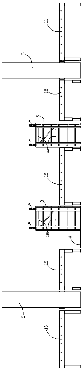
[0026] Such as figure 1 As shown, a production system for welding H-shaped steel includes a conveying roller table 1, an assembly machine 2 and a turning device 3 for turning over H-shaped steel; The conveying direction of the roller table 1 is provided with two, and the two turning devices 3 are all located between the two assembly machines 2; the distance between the two assembly machines 2 is greater than that of the H-beam to be welded. The maximum length, and the distance between the two overturning devices 3 is less than the minimum length of the H-shaped steel to be welded; the conveying roller table 1 includes the first conveying roller table 11, the second conveying roller table 12 and the third conveying roller table 13, the The first conveying roller table 11 and the third conveying roller table 13 are respectively connected and arranged on the two sides of the two assembly machines 2 facing away from each other. On the input side of the erecting machine 2, the thi...

Embodiment 2

[0049] In this embodiment, its main structure is the same as that of Embodiment 1, and will not be described again. The main difference between this embodiment and Embodiment 1 is:

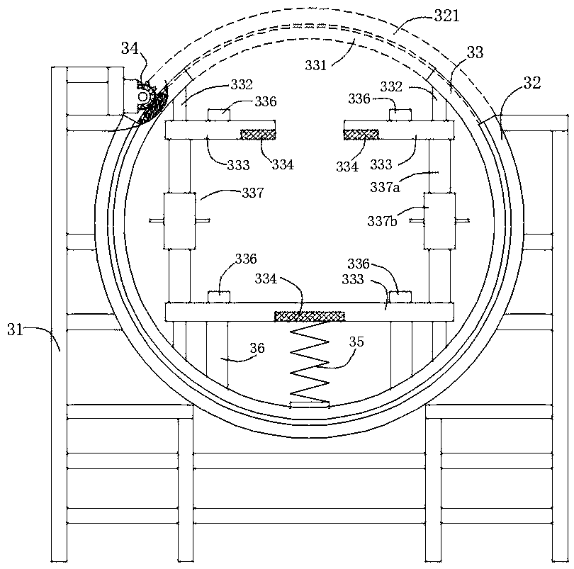
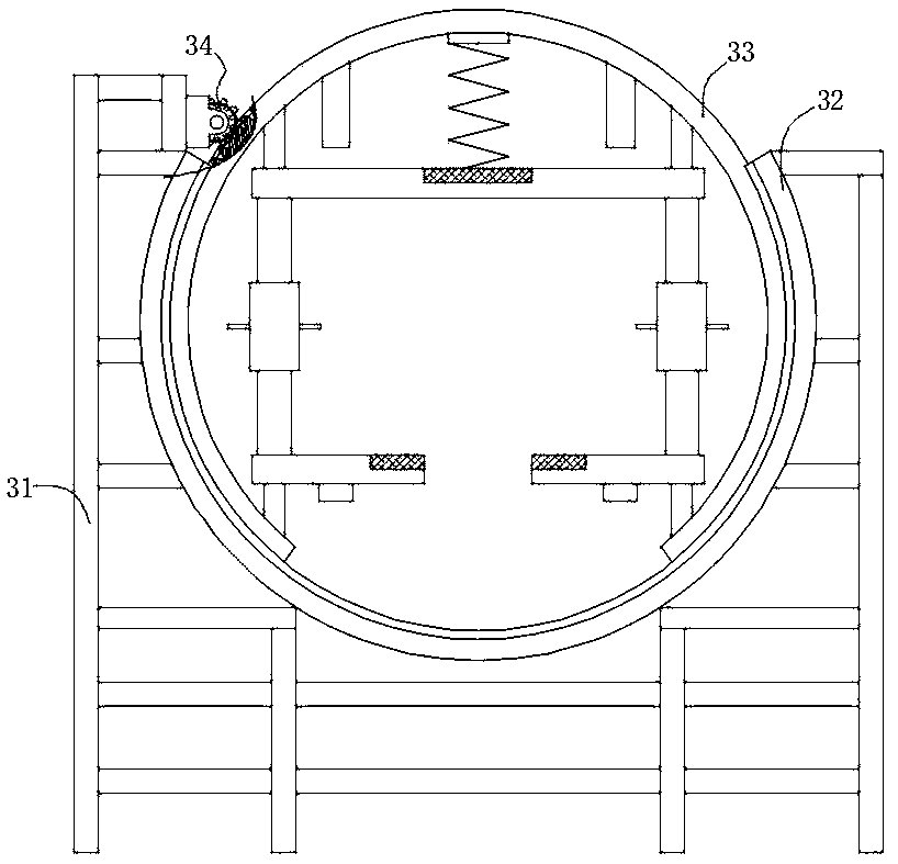
[0050] The locking adjustment mechanism 337 includes two support sleeves 337a sleeved on the support rod 332, and the two support sleeves 337a can move along the length direction of the support rod; the opposite ends of the two support sleeves 337a are provided with The connecting threads that rotate in opposite directions are connected through the adjusting sleeve 337b that is threaded. The support rod 332 has a limit slot arranged along the length direction, and the support sleeve has a limit screw arranged radially through, and the end of the limit screw can movably extend into the limit slot. Inside.

[0051] The two supporting parts 333 are respectively installed at the two ends of the two supporting sleeves 337a facing away from each other, and the two supporting parts located at the end of...


PUM


Abstract

The invention discloses a production system for welding H-shaped steel. The production system comprises a roll gang and assembly machines, and further comprises turnover devices which are arranged onthe output side of the assembly machines in a linked manner. Each turnover device comprises a turnover support, wherein two turnover tracks which are in a circular ring shape as a whole and a rollingframe are arranged on the turnover support, a first notch is horizontally formed above the turnover tracks, a second notch is formed in the rolling frame, two sides of the second notch are each provided with a supporting rod perpendicular to the plane where the second notch is located, two ends of the supporting rods are connected to the inner side of the rolling frame and provided with bearing parts perpendicularly arranged inwards, the distance between the bearing parts at the two ends is equal to the width of a web, electromagnets for fixing flanges are installed on the bearing parts, and aturnover driving mechanism for driving the rolling frame to rotate around the turnover tracks is installed on the turnover support. The production system has the advantages of being reasonable in structural design, simple in operation process, beneficial to reducing the labor intensity and improving the assembly welding efficiency, and the like.

Description

technical field [0001] The invention relates to the technical field of building material production and processing, in particular to a production system for welding H-shaped steel. Background technique [0002] H-shaped steel is an economical cross-section high-efficiency profile with more optimized cross-sectional area distribution and a more reasonable strength-to-weight ratio. It is named because its cross-section is the same as the English letter "H". Since all parts of the H-shaped steel are arranged at right angles, the H-shaped steel has the advantages of strong bending resistance in all directions, simple construction, cost saving and light structural weight, and has been widely used. [0003] Welding H-shaped steel is to cut the strip steel with suitable thickness into suitable width, and weld the flange and web together on the continuous welding unit. At present, there are two welding methods for welding H-shaped steel. One is to place the web horizontally, and sp...

Claims


Application Information

Patent Timeline
Patent Type & Authority Applications(China)
IPC IPC(8): B23K37/00B23K37/047B23K37/04
CPCB23K37/00B23K37/047B23K37/0426
Inventor 徐良春
Owner 重庆本浩建设工程有限公司
Why Eureka
Try Eureka