
Pile foundation structure and construction method thereof

A construction method and pile foundation technology, which can be applied to foundation structure engineering, sheet pile walls, buildings, etc., can solve the problems of low concrete strength of the pile body, long construction period of cast-in-place piles, and low bearing capacity of single piles, etc. Restricted by the site, the effect of simple construction

Active Publication Date: 2020-08-11
广东裕基建筑工程有限公司
View PDF6 Cites 2 Cited by
  • Summary
  • Abstract
  • Description
  • Claims
  • Application Information

AI Technical Summary

Problems solved by technology

Therefore, compared with prestressed pipe piles, bored piles have the characteristics of no vibration, no impact of soil compaction, and little impact on surrounding buildings, but the strength of the pile concrete is lower, the bearing capacity of a single pile is lower, and the settlement is larger
[0005] Because the existing prefabricated piles will squeeze the surrounding soil, and the cast-in-situ piles have a long construction period from pouring concrete to curing, so the present invention combines the advantages and disadvantages of the existing prefabricated piles and cast-in-place piles to create A pile foundation structure has been developed, which not only combines the advantages of prefabricated piles with low cost, short construction period, guaranteed quality and cast-in-place piles not limited by soil quality and site conditions, but also reduces or even eliminates the extrusion deformation or even damage of prefabricated piles to the surrounding soil. At the same time, the shortcoming of long construction period of cast-in-situ piles can also be alleviated

Method used


Image

  • Pile foundation structure and construction method thereof
  • Pile foundation structure and construction method thereof
  • Pile foundation structure and construction method thereof

Examples


Embodiment Construction

[0043] The present invention will be described in further detail below in conjunction with the accompanying drawings.

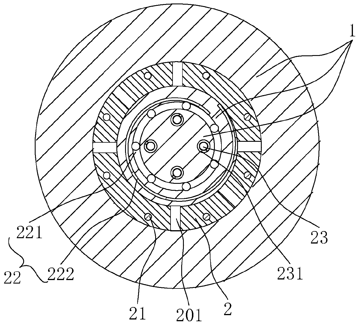
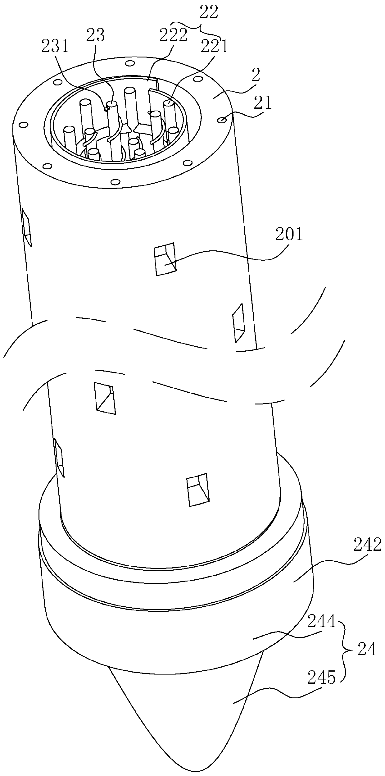
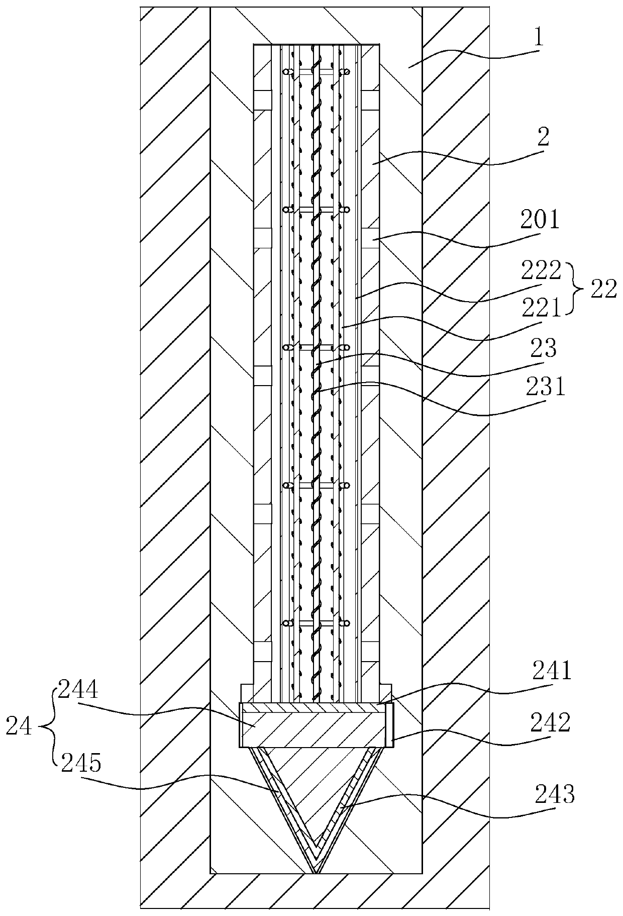
[0044] refer to figure 1 , figure 2 , a pile foundation structure, including cast-in-place pile 1, cast-in-place pile 1 is formed by pouring grout, and can be fixed with borehole pouring according to the shape of the borehole on the soil. The cast-in-situ pile 1 is embedded with a prefabricated pile core 2, and the prefabricated pile core 2 is set in the cast-in-place pile 1, which can increase the structural strength of the cast-in-place pile 1, and at the same time, the cast-in-situ pile 1 can shorten the curing time and shorten the construction period of the pile foundation; the prefabricated pile core 2 is provided with a cavity inside, and the prefabricated pile core 2 is provided with a steel frame 22 inside the cavity, and the steel frame 22 can play an internal support and reinforcement role for the pile foundation, making the structure of the pile ...


PUM


Abstract

The invention relates to the technical field of pile foundation construction, in particular to a pile foundation structure and a construction method thereof. The pile foundation structure comprises acast-in-place pile, wherein a prefabricated pile core is embedded in the cast-in-place pile, a cavity is formed in the prefabricated pile core, and a steel reinforcement framework is arranged in the cavity of the prefabricated pile core. The construction method of the pile foundation comprises the following steps: S1, forming a hole in situ; S2, placing a prefabricated pile core in the hole, wherein a distance is reserved between the prefabricated pile core and the inner side wall of the drilled hole; S3, placing the steel reinforcement framework in the cavity of the prefabricated pile core; S4, pouring slurry, so that the prefabricated pile core is immersed in the slurry; and S5, enabling the anti-seismic steel bars to sink into the cavity of the prefabricated pile core. The constructionmethod combines the advantages and disadvantages of existing precast piles and cast-in-place piles, has the advantages of being economical in manufacturing cost, short in construction period, guaranteed in quality and not limited by site conditions, can eliminate the defect that the precast piles deform or even are damaged due to extrusion on surrounding soil, and also reduces the defect that theconstruction period of the cast-in-place pile is long.

Description

technical field [0001] The invention relates to the technical field of pile foundation construction, in particular to a pile foundation structure and a construction method thereof. Background technique [0002] According to different construction methods, piles can be divided into prefabricated piles and cast-in-situ piles. Both are widely used in foundations with weak soil and thick burial. They have the characteristics of high bearing capacity, good stability, small settlement, and less consumables. They can effectively meet the requirements of buildings for foundation strength, deformation and stability. The two types of piles have their own characteristics, different construction methods, different mechanical equipment and construction techniques, different mechanisms of action between piles and soil, and different scopes of application. [0003] Prefabricated piles have the advantages of economical cost, short construction period, and guaranteed quality, but they have ...

Claims


Application Information

Patent Timeline
IPC IPC(8): E02D27/12E02D5/50
CPCE02D27/12E02D5/50
Inventor 刁邦宏陈军培张龙武徐志海袁兴明李跃丰高双
Owner 广东裕基建筑工程有限公司
Learn More