
Grounding method and grounding system of gil power shield tunnel

A grounding method and technology of shield pipes, which are applied in earth drilling, hydropower generation, underground chambers, etc., can solve the problems of high cost cables, high grounding system design requirements, and small short-circuit current

Active Publication Date: 2022-08-09
CHINA POWER ENG CONSULTING GRP CORP EAST CHINA ELECTRIC POWER DESIGN INST
View PDF0 Cites 0 Cited by
  • Summary
  • Abstract
  • Description
  • Claims
  • Application Information

AI Technical Summary

Problems solved by technology

The main advantage of GIL equipment lies in its large transmission capacity, but the cost is higher than that of cables. Usually, the advantages of GIL equipment can be fully utilized at a voltage level of 500kV and above. At present, my country's 500kV and above power grids usually have the characteristics of large short-circuit current, so GIL tubes The corridor has high requirements on the design of the grounding system
[0003] However, the current grounding system designed for the requirements of pipe racks is mainly for comprehensive pipe racks or cable pipe racks. However, due to the relatively small short-circuit current of this type of pipe rack project, a special grounding body is usually laid on the pipe rack and used to work on both sides. However, if the short-circuit current is too large, or the resistivity of the working well area is high, the grounding scheme will be difficult, and additional measures should be taken to solve the problem.

Method used


Image

  • Grounding method and grounding system of gil power shield tunnel
  • Grounding method and grounding system of gil power shield tunnel
  • Grounding method and grounding system of gil power shield tunnel

Examples


Embodiment Construction

[0027] The technical solutions in the embodiments of the present invention will be clearly and completely described below with reference to the accompanying drawings in the embodiments of the present invention. Obviously, the described embodiments are only a part of the embodiments of the present invention, but not all of the embodiments. Based on the embodiments of the present invention, all other embodiments obtained by those of ordinary skill in the art without creative efforts shall fall within the protection scope of the present invention.

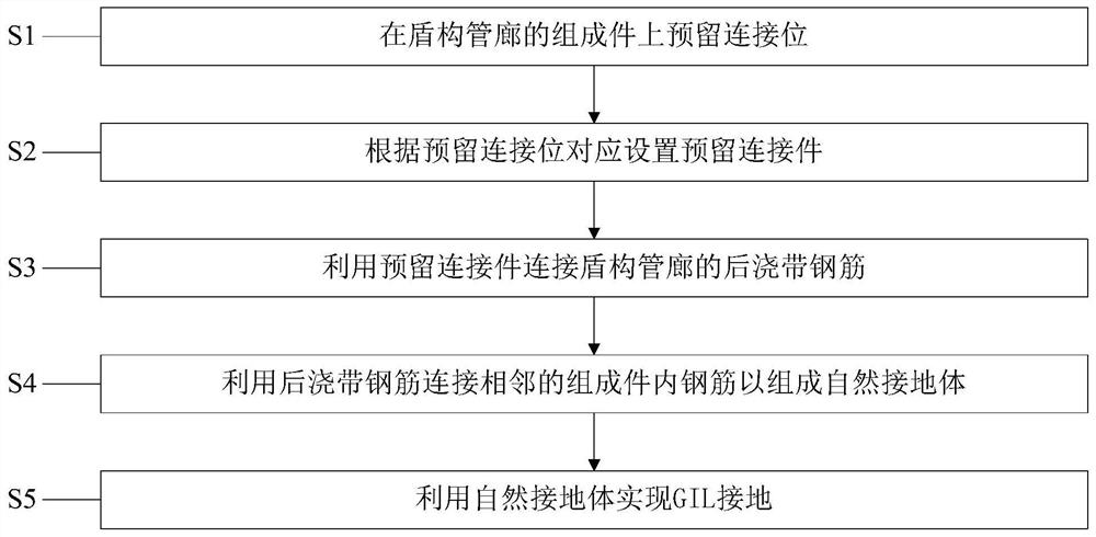
[0028] figure 1 This is a flowchart of the grounding method of the GIL power shield tunnel tunnel according to the embodiment of the present invention.

[0029] like figure 1 As shown, the grounding method of the GIL power shield tunnel tunnel according to the embodiment of the present invention includes the following steps:

[0030] S1, reserve connection positions on the components of the shield tunnel.

[0031] In one embodiment...


PUM


Abstract

The invention provides a grounding method and a grounding system for a GIL power shield tunnel tunnel, wherein the grounding method includes the following steps: reserving connection positions on the components of the shield tunnel tunnel; setting correspondingly according to the reserved connection positions Reserve connectors; use the reserved connectors to connect the post-cast steel bars of the shield tunnel gallery; use the post-cast tape bars to connect the steel bars in the adjacent components to form a natural grounding body; use the natural grounding body to realize GIL grounding. The invention can ensure the maximization of the grounding conductor area, so as to reduce the grounding impedance value, thereby reducing the design investment of the special grounding network while ensuring the safety of the personnel, and has simple scheme and convenient construction.

Description

technical field [0001] The invention relates to the technical field of grounding system design, in particular to a grounding method for a GIL power shield tunnel tunnel and a grounding system for a GIL power shield tunnel tunnel. Background technique [0002] At present, due to limited land resources and enhanced public awareness of environmental protection, land acquisition for overhead line corridors is becoming more and more difficult, while the scale of cities increases, and the density of urban power consumption is also increasing. It is necessary to lay high voltage and large capacity underground in urban areas. Transmission lines, these factors are conducive to the application of GIL (Gas-Insulated transmission Lines, gas-insulated metal-enclosed lines) in power systems. The main advantage of GIL equipment is that it has large transmission capacity, but the cost is higher than that of cables. Usually, the advantages of GIL equipment can be fully utilized at the voltag...

Claims


Application Information

Patent Timeline
Patent Type & Authority Patents(China)
IPC IPC(8): E21D9/06E21D11/08E21D11/10H01R4/66
CPCE21D9/06E21D11/08E21D11/10H01R4/66Y02E10/20
Inventor 熊赟超王卫华俞正乐党救张景锋潘益华
Owner CHINA POWER ENG CONSULTING GRP CORP EAST CHINA ELECTRIC POWER DESIGN INST
Learn More