Construction method of new-air system built in kitchen ventilator and door pocket

A construction method and fresh air system technology, applied in ventilation systems, air-conditioning systems, and oil fume removal, etc., can solve problems such as complex construction technology, poor smoke exhaust effect of range hoods, and insufficient fresh air supply, so as to reduce air pollution and smoke exhaust The effect of better effect and short air circulation path

Active Publication Date: 2020-08-11
王庆虎
View PDF9 Cites 0 Cited by
  • Summary
  • Abstract
  • Description
  • Claims
  • Application Information

AI Technical Summary

Problems solved by technology

[0006] Based on the above-mentioned defects of the prior art, the present invention proposes a construction method of a fresh air system built inside the range hood and on the door cover, to solve the problem of poor smoke exhaust effect, insufficient supply of fresh air and complex construction techniques of the existing range hood The problem

Method used


Image

  • Construction method of new-air system built in kitchen ventilator and door pocket
  • Construction method of new-air system built in kitchen ventilator and door pocket
  • Construction method of new-air system built in kitchen ventilator and door pocket

Examples


Embodiment 1

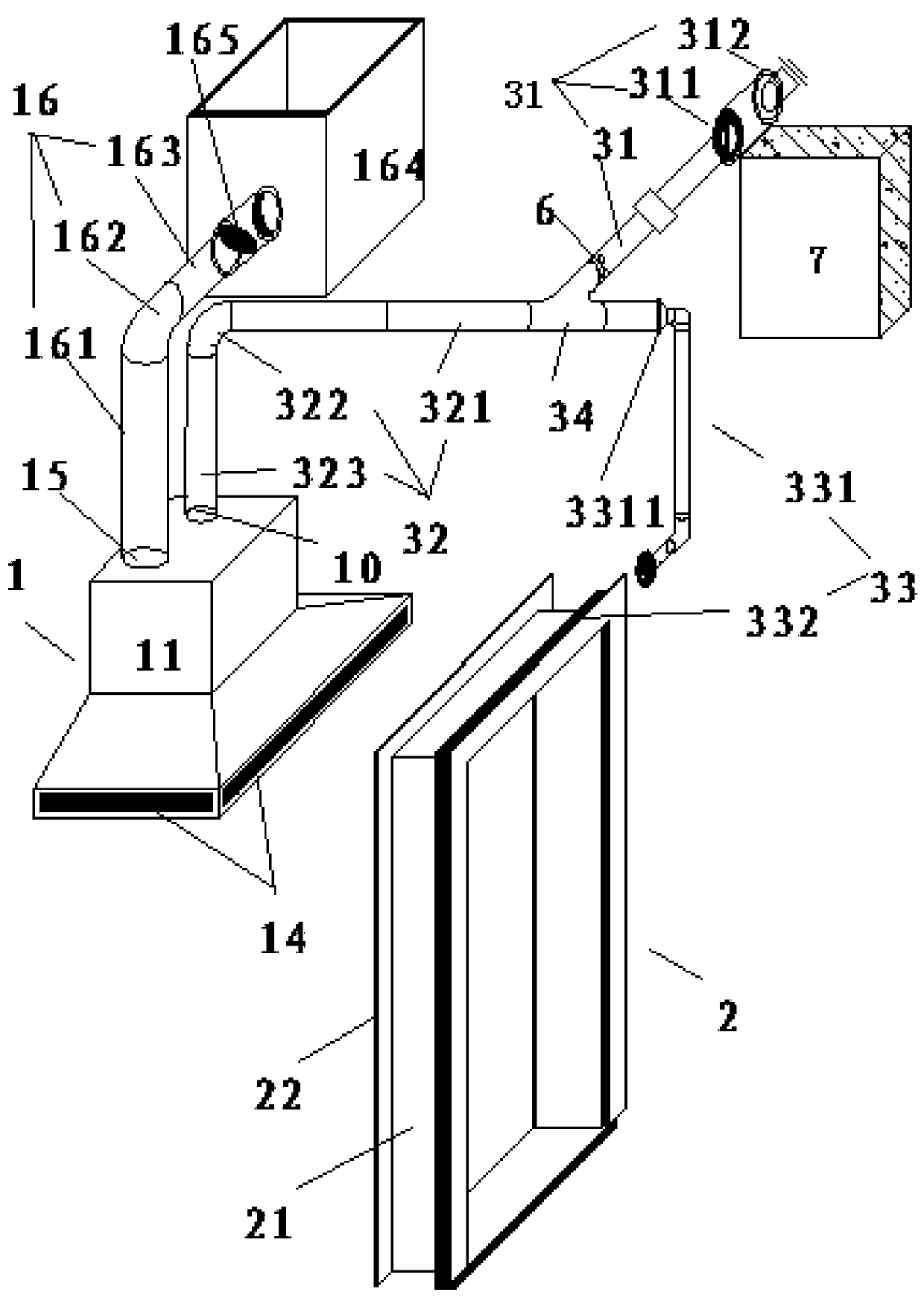
[0045] Such as figure 1 , as shown in 3-10, a fresh air system built in the range hood and the door cover of the present invention includes a kitchen range hood 1, a kitchen door cover 2 and a fresh air duct 3, and a fresh air fan 6 is arranged in the fresh air duct 3. The fresh air duct 3 includes an air inlet pipe 31 , a range hood fresh air duct 32 and a door pocket fresh air duct 33 . In this example, if figure 1 As shown, the fresh air fan 6 is only arranged in the air inlet pipe 31 . One end of the air inlet pipe 31 is provided with an outer wall airtight casing 311 and a rainproof and ventilating valve 312 sequentially from the inside to the outside, and the other end is connected with the fresh air duct 32 of the range hood and the fresh air duct 33 of the door pocket through the fresh air tee 34 respectively. An air filter device 341 is also arranged on the fresh air tee 34 connected to the air inlet pipe 31 . The range hood fresh air duct 32 is composed of a horiz...

Embodiment 2

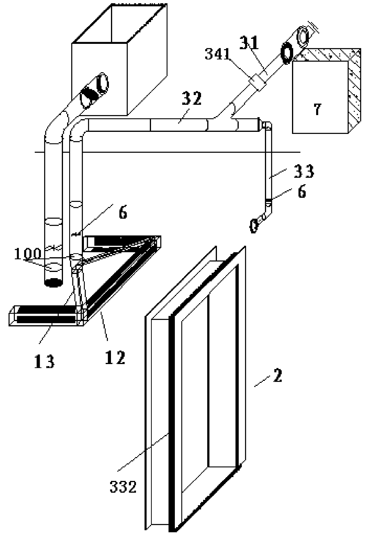
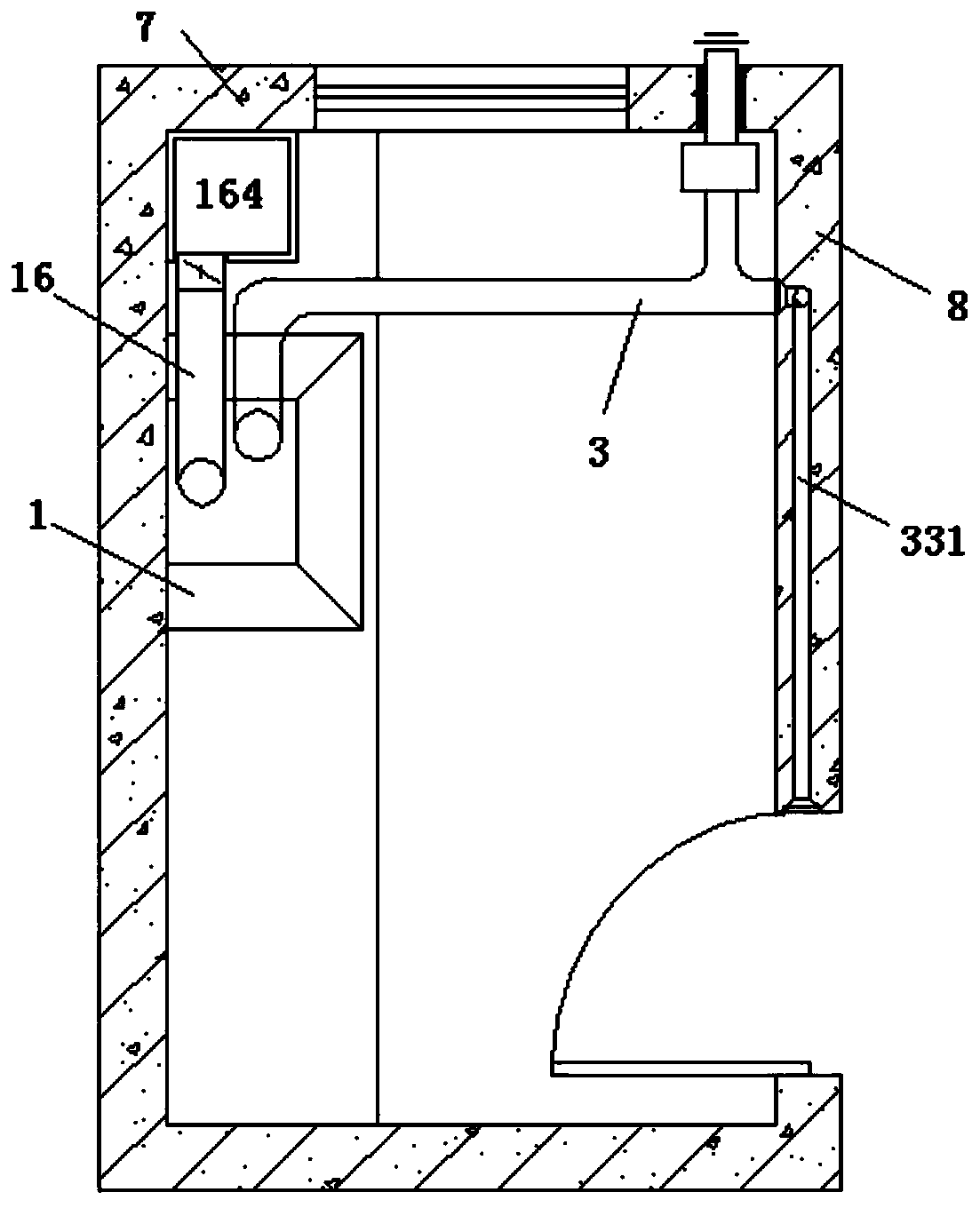
[0071] Such as Figure 2-10 As shown, in this embodiment, the fresh air fan 6 is respectively arranged in the vertical air duct 323 and the L-shaped embedded wall air duct 331 . The kitchen range hood linkage line is connected to the above-mentioned vertical air duct 323 and the fresh air fan 6 in the L-shaped pre-embedded wall air duct 331 at the same time. Other structures and construction methods are the same as in Embodiment 1, and will not be described in detail here.

[0072]In this embodiment, the fresh air from the kitchen enters the room through the rain-proof and ventilating valve 312 inside the outer wall, and the air duct of the airtight casing 311 on the outer wall enters the room, is filtered by the air filter device 341, and is divided into two paths through the fresh air pipe, and is sent to the fresh air of the range hood respectively. Duct 32 and door casing fresh air duct 33.

[0073] The first way: range hood fresh air:

[0074] The fresh air of the rang...


PUM


Abstract

The invention relates to a construction method of a new-air system built in a kitchen ventilator and a door pocket, and belongs to the technical field of construction technologies of new-air systems.The new-air system comprises the kitchen ventilator, the kitchen door pocket and a new-air pipeline, wherein a new-air fan is arranged in the new-air pipeline, the new-air pipeline comprises an air inlet pipe, a kitchen ventilator new-air pipeline and a door pocket new-air pipeline, the door pocket new-air pipeline comprises an L-shaped pre-embedded wall air pipe and a door pocket new-air pipe sleeve, and the kitchen ventilator comprises a kitchen ventilator shell and a new air distributing pipe arranged at the outer edge inside the kitchen ventilator shell. The construction method comprises the following steps of structural pre-embedding; factory processing, wherein processing of the kitchen ventilator and processing of the kitchen door pocket are involved; installation, debugging and delivery of the equipment; and installation and fixation. The kitchen ventilator has an excellent effect of smoke discharge, supplies sufficient new air, and does not produce indoor peculiar smell, and meanwhile, the construction period is short.

Description

technical field [0001] The invention relates to a construction method of a fresh air system, in particular to a construction method of a fresh air system built inside a range hood and on a door cover, and belongs to the technical field of fresh air system construction technology. Background technique [0002] With the development of science and technology, building doors and windows are gradually updated, their performance is steadily increasing, their airtightness performance is gradually improving, and the infiltration of cold wind is gradually decreasing. The large air volume in the range hood market has become a hot spot. [0003] The existing range hood does not have a fresh air device. When the range hood is turned on to exhaust smoke, due to the high air tightness of the building, the small pores of the doors and windows of the building, the infiltration of outdoor air is insufficient, the air flow replenishment is less than the design value of the hood air volume, t...

Claims


Application Information

Patent Timeline
Patent Type & Authority Applications(China)
IPC IPC(8): F24F7/08F24F3/16F24F13/28F24C15/20E06B1/34E06B7/10
CPCE06B1/34E06B7/10E06B2007/023F24C15/2035F24F7/08F24F13/28F24F8/10F24F8/108
Inventor 王庆虎
Owner 王庆虎
Why Eureka
Try Eureka