Rotary cylinder model test device

A model test device and cylinder technology, which is applied in the direction of measuring device, aerodynamic test, machine/structural component test, etc., can solve the problems such as difficult to meet the demand of speed, reduce test cost, increase stiffness, and facilitate operation Effect

Pending Publication Date: 2020-08-11
CHINA SHIP SCIENTIFIC RESEARCH CENTER (THE 702 INSTITUTE OF CHINA SHIPBUILDING INDUSTRY CORPORATION)
View PDF0 Cites 2 Cited by
  • Summary
  • Abstract
  • Description
  • Claims
  • Application Information

AI Technical Summary

Problems solved by technology

Therefore, the smaller the radius of the rotor model, the higher the test speed required, and the existing test device is difficult to meet the demand for speed due to its own structural limitations

Method used


Image

  • Rotary cylinder model test device
  • Rotary cylinder model test device
  • Rotary cylinder model test device

Examples


Embodiment 1

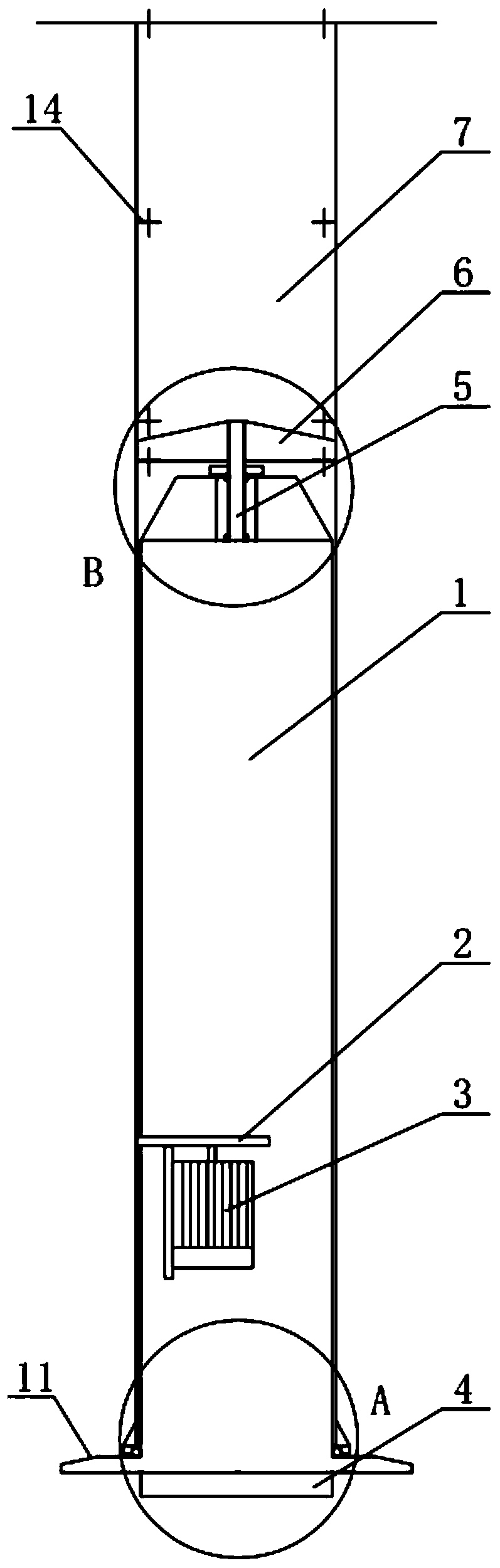
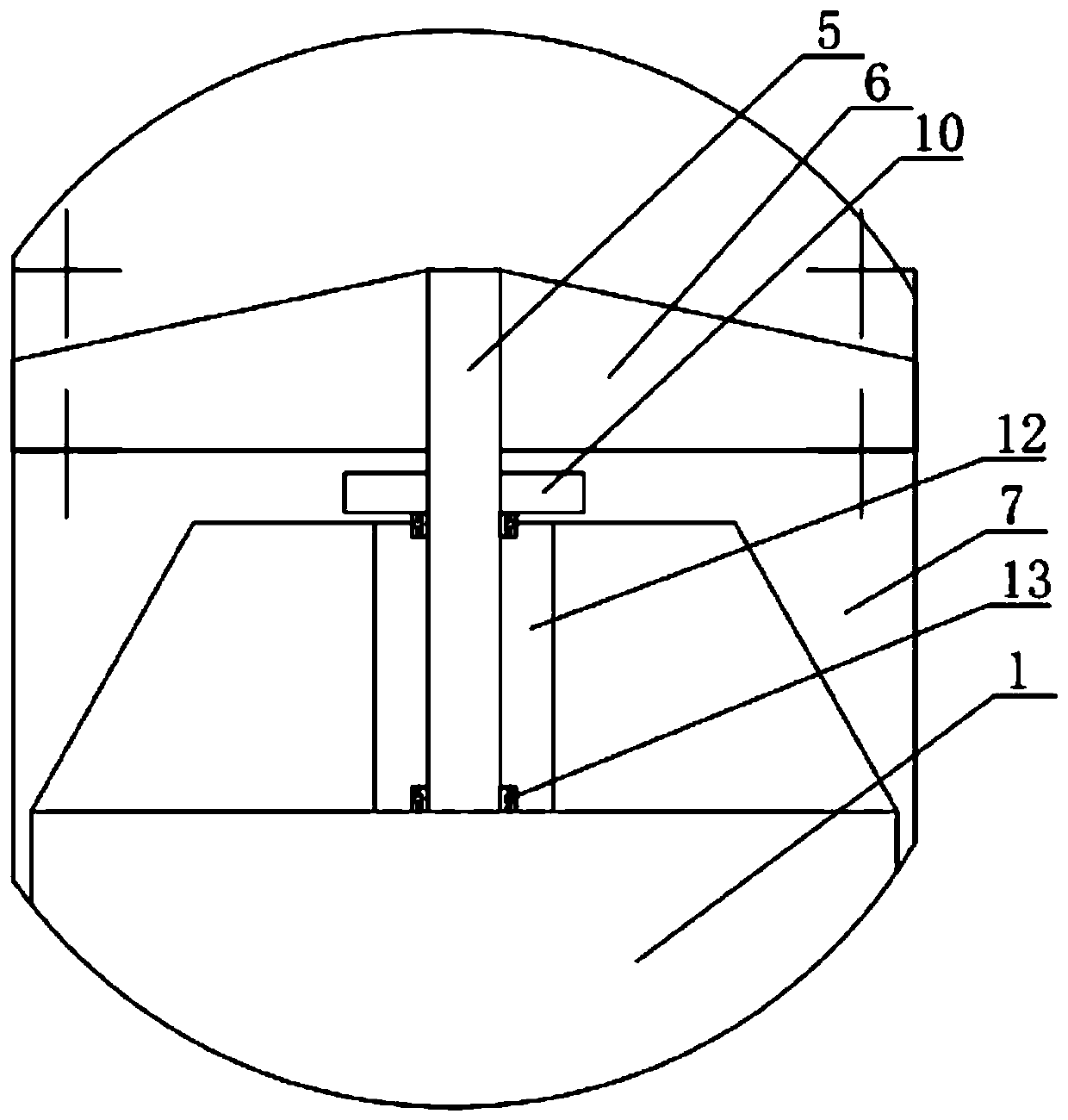
[0040] The support tower 1 is accommodated inside the cylinder 7, and there is a gap between the outer circumference of the support tower 1 and the inner wall of the cylinder 7; a large bearing is installed between the lower part of the circumference of the support tower 1 and the cylinder 7.

[0041] The large bearing is an angular contact ball bearing, which is installed between the inner wall of the cylinder 7 and the outer wall of the support tower 1; the outer ring of the angular contact ball bearing is fixed to the inner wall of the cylinder 7, and the angular contact ball bearing The inner ring is fixed to the outer wall of the support tower 1; the angular contact ball bearing provides the cylinder 7 with circumferential constraints and fulcrums relative to the support tower 1.

Embodiment 2

[0043] The support tower 1 is accommodated inside the cylinder 7, and there is a gap between the outer circumference of the support tower 1 and the inner wall of the cylinder 7; a large bearing is installed between the lower part of the circumference of the support tower 1 and the cylinder 7.

[0044] A base 11 extends from the bottom of the supporting tower 1 in the circumferential direction, and the diameter of the base 11 is larger than that of the supporting tower 1 and the cylinder 7 .

[0045] The large bearing is a thrust bearing, and the thrust bearing is installed between the bottom surface of the cylinder 7 and the base 11 of the support tower 1; Fixed installation; the thrust bearing provides the cylinder 7 with circumferential restraint and fulcrum relative to the support tower 1 .

Embodiment 3

[0047] The support tower 1 is accommodated inside the cylinder 7, and there is a gap between the outer peripheral surface of the support tower 1 and the inner wall of the cylinder 7; a ball mechanism is installed between the lower part of the peripheral surface of the support tower 1 and the cylinder 7.

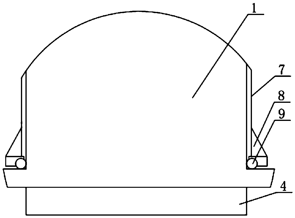
[0048] The bottom of the support tower 1 extends toward the circumferential direction with a base 11, and the diameter of the base 11 is greater than the diameter of the support tower 1 and the cylinder 7; as figure 2 As shown, the structure of the ball mechanism is as follows: it includes a bracket 8 installed circumferentially along the lower edge of the outer peripheral surface of the cylinder 7, and a plurality of balls 9 are installed circumferentially between the bracket 8 and the supporting tower 1; 9 is snapped into the corresponding hole on the bracket 8, and the single ball 9 rotates relative to the bracket 8; 1. The upper surface of the base 11 is in contact at th...


PUM


Abstract

The invention relates to a rotary cylinder model test device which comprises a supporting tower. A cylinder rotatably sleeves the circumferential outer side of the supporting tower; a driver is fixedly installed in the supporting tower, a runner is installed at the output end of the driver, and the circumferential edge of the runner extends out of the supporting tower and is attached to the innerwall face of the cylinder. A rotating shaft is rotatably arranged on the upper part of the supporting tower, the upper end of the rotating shaft extends upwards out of the supporting tower, and a rotating disc is installed at the end of the upper end of the rotating shaft and fixedly installed on the inner wall face of the cylinder in the circumferential direction; a force balance is mounted on the bottom surface of the supporting tower; during use, the test device is installed on the wind tunnel test ground through the force balance; a short cylinder is installed above the cylinder through afastener to obtain a rotating cylinder with a preset length-diameter ratio, a driver drives a rotating wheel to rotate, the rotating wheel drives the cylinder attached to the rotating wheel to rotatethrough circumferential surface friction force, the rotary cylinder integrally rotates, and therefore rotating torque is measured through a torquemeter, and lifting resistance is measured through a force balance. The device is used for a rotary cylinder model test, rotation is reliable and stable, and the test effect is powerfully guaranteed.

Description

technical field [0001] The invention relates to the technical field of rotating cylinder test equipment, in particular to a rotating cylinder model test device. Background technique [0002] The model test method is one of the main technical means to evaluate the aerodynamic characteristics of the equipment, and the rotating cylinder turbulence is one of the more difficult model tests. The existing rotating cylinder turbulence tests are all used to simulate the rotating cylinder in an ideal state. The rotating cylinder is suspended in the air for the test. The test speed is low and it is difficult to achieve a high speed. [0003] Marine wind-assisted rotor is a device that uses wind energy to provide boosting force for ship navigation by rotating a cylinder, thereby realizing energy-saving and emission-reducing devices for ships. It is actually a cantilever structure with one end fixed on the deck. The marine wind-assisted rotor in use is affected by the atmospheric bounda...

Claims


Application Information

Patent Timeline
Patent Type & Authority Applications(China)
IPC IPC(8): G01M9/08G01M9/06G01M9/04
CPCG01M9/04G01M9/062G01M9/08
Inventor 刘希洋陈京普郭峰山胡江平胡世良
Owner CHINA SHIP SCIENTIFIC RESEARCH CENTER (THE 702 INSTITUTE OF CHINA SHIPBUILDING INDUSTRY CORPORATION)
Why Eureka
Try Eureka