Conducting wire peeling machine with scrap suction cylinder convenient to install

A technology of stripping machine and wire, applied in cable installation, cable installation device, equipment for dismantling/armoring cables, etc. Effect

Active Publication Date: 2020-08-11
上海发之源电气有限公司
View PDF12 Cites 2 Cited by
  • Summary
  • Abstract
  • Description
  • Claims
  • Application Information

AI Technical Summary

Problems solved by technology

[0008] The above-mentioned existing technical solutions have the following defects: when installing the chip suction tube 3, there are strict requirements on the position of the chip suction tube 3, such as: the height of the chip suction tube 3 in the vertical direction or the orientation of the chip suction tube 3 The length that the peeling knife 2 extends, then when installing the chip suction tube 3, the fixed block 4 is installed in the fixed position at first, then the chip suction tube 3 is inserted into the fixed block 4, and then the chip sucti

Method used


Image

  • Conducting wire peeling machine with scrap suction cylinder convenient to install
  • Conducting wire peeling machine with scrap suction cylinder convenient to install
  • Conducting wire peeling machine with scrap suction cylinder convenient to install

Examples


Embodiment Construction

[0039] The present invention will be described in further detail below in conjunction with the accompanying drawings.

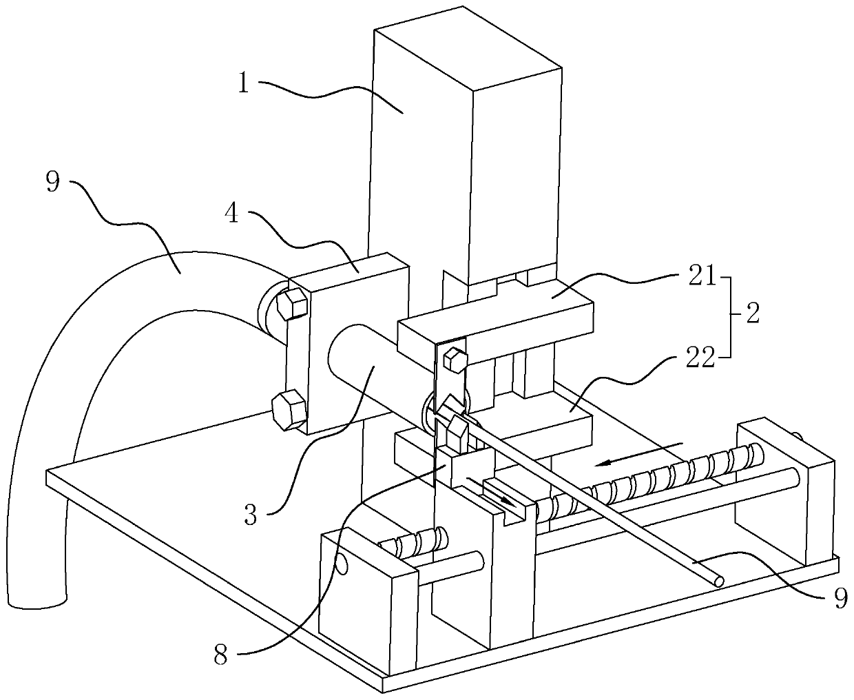
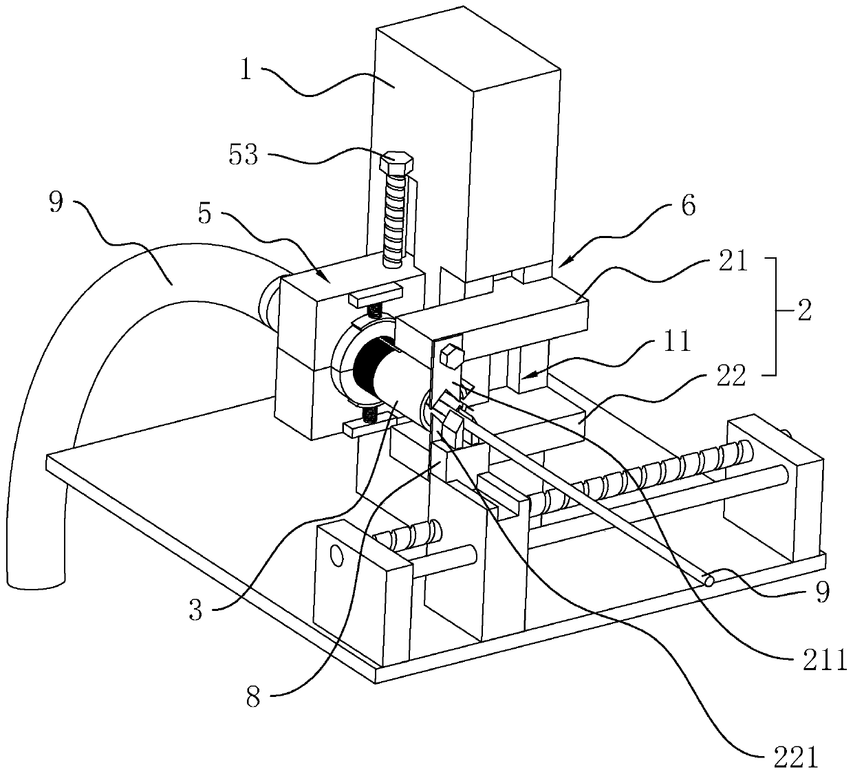
[0040] See attached figure 2 , is a kind of wire stripping machine that is convenient for installing a dust suction cylinder disclosed by the present invention, including a base 1 and a stripping knife 2 slidably arranged on the base 1 .

[0041] A vertical side of the base 1 is provided with a vertically extending slide rail 11, and the peeling knife 2 includes an upper knife 21, a lower knife 22 positioned below the upper knife 21 and a cutter driving mechanism 6, and the upper knife 21 is provided with an upper The blade 211 and the lower blade 22 are provided with a lower blade 221 . Moreover, both the upper cutter 21 and the lower cutter 22 are slidably connected to the slide rail 11 and both can move up and down along the slide rail 11 . That is, the clamp 8 clamps the wire 9 along the lead screw and pushes it between the upper blade 211 and the lowe...


PUM


Abstract

The invention relates to the technical field of wire harness peeling equipment, and discloses a conducting wire peeling machine with a scrap suction cylinder convenient to install. The conducting wirepeeling device comprises a base and a peeling knife arranged on the base in a sliding manner, wherein the base is also provided with a scrap suction cylinder with the cylinder opening aligned with the peeling knife, a fixed clamping seat is also arranged on the vertical side surface of the base, a through groove penetrating through the fixed clamping seat is formed in the fixed clamping seat, thethrough groove is aligned with the peeling knife, the scrap suction cylinder is inserted into the through groove and can move along the axis of the through groove, an adjusting ring with the axis coinciding with the axis of the through groove is further arranged on the fixed clamping seat and located at the through groove and can rotate around the axis of the through groove, the inner side wall of the adjusting ring is in threaded connection with the outer side wall of the scrap suction cylinder, and the scrap suction cylinder can move in the through groove by rotating the adjusting ring. When the position of the scrap suction cylinder is installed and adjusted, the scrap suction cylinder can be moved only by screwing the adjusting ring, so that rotation of the scrap suction cylinder is avoided, operation is convenient, and the installation difficulty is reduced.

Description

technical field [0001] The invention relates to the technical field of wire harness stripping equipment, in particular to a wire stripping machine which is convenient for installing a dust suction cylinder. Background technique [0002] The wiring harness is composed of an insulating sheath, terminal blocks, wires and insulating wrapping materials. With the rapid development of automation technology, the market demand for wire harness processing is increasing. In the process of making and assembling the wire harness, the first step is to peel off the rubber covering the front end of the wire to leak out the copper wire, and then carry out the assembly process such as crimping the terminal. At present, a stripping machine is usually used for stripping the wires. [0003] See attached figure 1 , the existing wire stripping machine comprises a base 1 and a stripping knife 2 arranged on the base 1 . [0004] Wherein, the peeling knife 2 includes an upper knife 21 and a lower...

Claims


Application Information

Patent Timeline
IPC IPC(8): H02G1/12H01R43/05
CPCH01R43/05H02G1/1217
Inventor 金浩李林平汪姚松
Owner 上海发之源电气有限公司
Why Eureka
Try Eureka