Heat cleaning equipment for adsorbing railway track metal substances through electromagnetic force
A technology for railway tracks and metal substances, which is applied in snow surface cleaning, cleaning methods, construction, etc., can solve the problems of metal wastes that are difficult to effectively clean up, easy to be adsorbed on rails, and cannot be completely removed, so as to improve the value of use , Protect normal operation, avoid thermal degaussing effect
- Summary
- Abstract
- Description
- Claims
- Application Information
AI Technical Summary
Problems solved by technology
Method used
Image
Examples
Embodiment 1
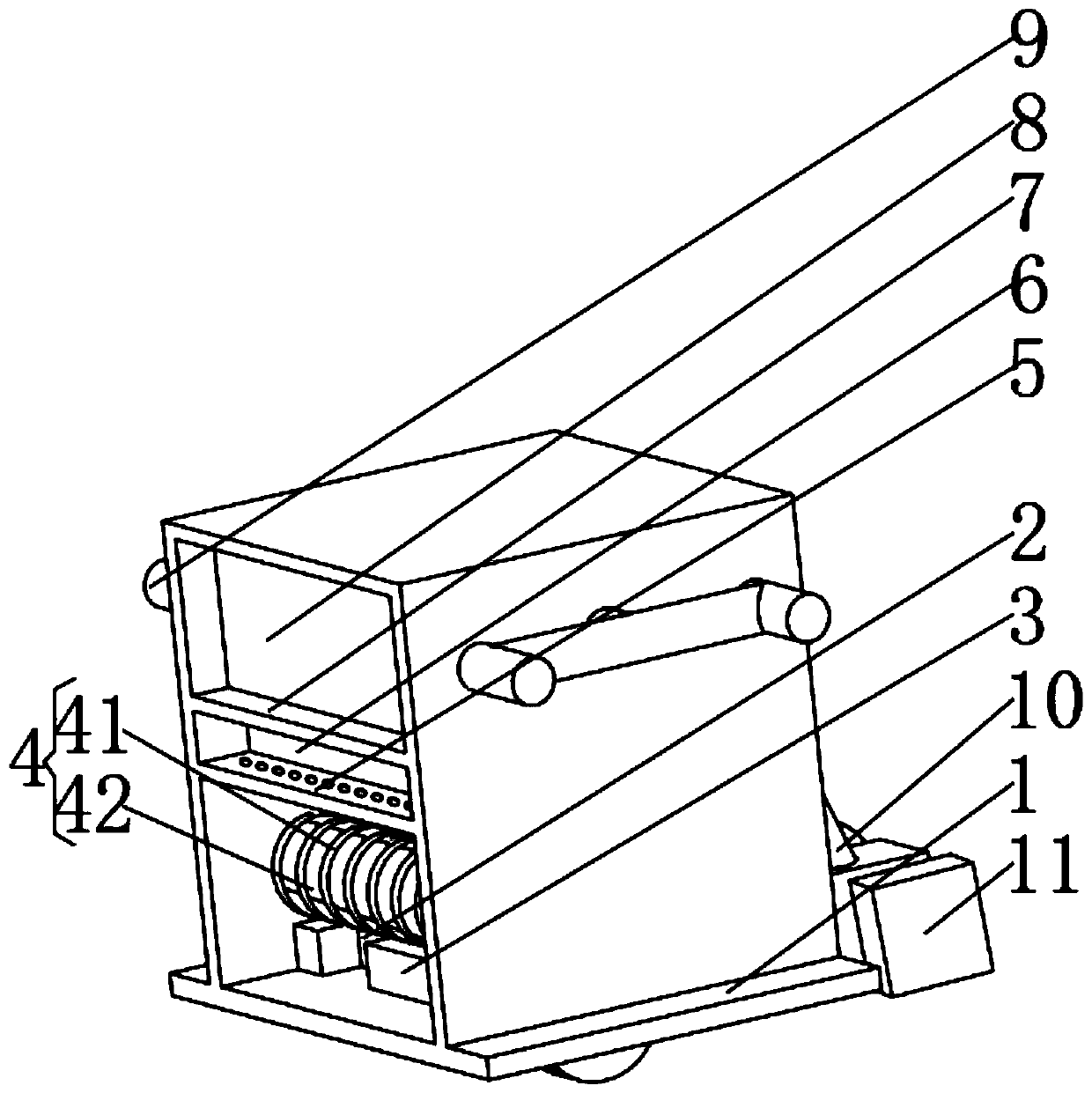
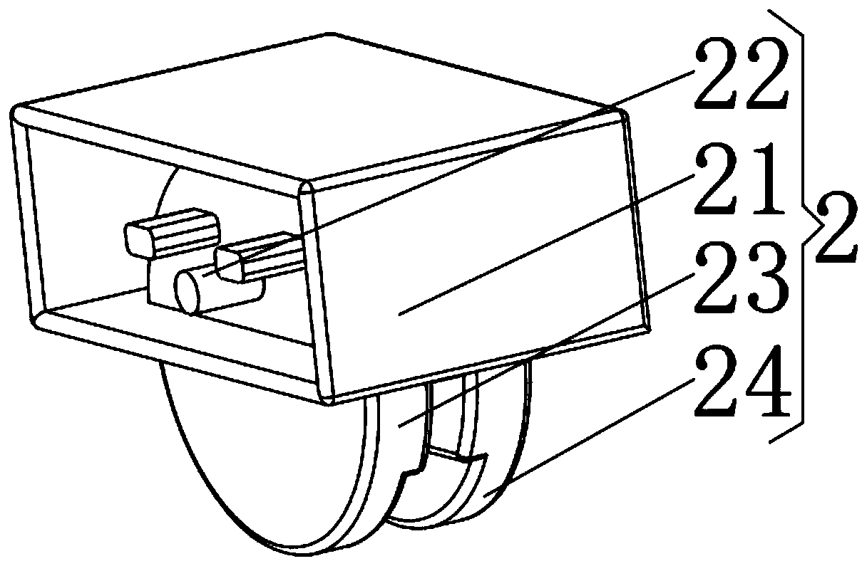
[0037] see Figure 1-2 , the present invention provides a technical solution: an electromagnetic force adsorption thermal cleaning equipment for railway track metal substances, including a protective outer box 1, the middle position of the bottom of the inner cavity of the protective outer box 1 is fixedly connected with a magnetic adsorption mechanism 2, and the protective outer box 1 The bottom of the inner cavity is located on both sides of the magnetic adsorption mechanism 2 and is fixedly connected with a magnetic cleaning mechanism 3. The inner walls on both sides of the protective outer box 1 are located above the magnetic adsorption mechanism 2 and are equipped with electromagnetic mechanisms 4. The inner walls on both sides of the protective outer box 1 are located on the electromagnetic mechanism 4. The heat insulation baffle 5 is fixedly connected on the top, and the side of the heat insulation baffle 5 away from the electromagnetic mechanism 4 is fixedly connected w...
Embodiment 2
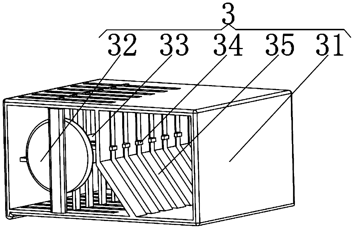
[0039] see Figure 1-5 The present invention provides a technical solution: the magnetic cleaning mechanism 3 includes an outer groove frame 31, a magnetic driver 32 is fixedly connected to the left side of the inner cavity of the outer groove frame 31, and a rotating rod 33 is connected to the back of the magnetic driver 32 in rotation, and the outside of the rotating rod 33 A cleaning shaft 34 is fixedly connected to the surface, and a separation plate 35 is fixedly connected to the right side of the top and bottom of the inner chamber of the outer frame 31 . The electromagnetic mechanism 4 includes an electromagnetic coil 41 , and an iron mandrel 42 is arranged on the inner surface of the electromagnetic coil 41 . The heat insulation baffle 5 includes a middle plate 51 , the upper surface and the lower surface of the middle plate 51 are fixedly connected with side plates 52 , and the side of the side plate 52 away from the middle plate 51 is provided with a strip 53 . The ...
Embodiment 3
[0041] see Figure 1-8 The present invention provides a technical solution: the magnetic shielding plate 7 includes a permalloy layer 71 , and the side of the permalloy layer 71 away from the thermal degaussing mechanism 6 is fixedly connected with a nickel-iron alloy layer 72 . The adjustment mechanism 10 includes a hydraulic cylinder 101, the output end of the hydraulic cylinder 101 is fixedly connected with a transfer bolt 102, and the outer surface of the transfer bolt 102 is movably connected with a strengthening pressure rod 103, and the middle position of the strengthening pressure rod 103 is provided with an adjustment channel 104, through which the adjustment channel The inner surface of the groove 104 is movably connected with the adapter bolt 102 . The drive mechanism 11 includes a central motor 111 , the output end of the central motor 111 is fixedly connected with a drive shaft 112 through a coupling, and the end of the drive shaft 112 away from the central motor ...
PUM
 Abstract
Description
Claims
Application Information
 - R&D
- Intellectual Property
- Life Sciences
- Materials
- Tech Scout
- Unparalleled Data Quality
- Higher Quality Content
- 60% Fewer Hallucinations
Browse by: Latest US Patents, China's latest patents, Technical Efficacy Thesaurus, Application Domain, Technology Topic, Popular Technical Reports.
© 2025 PatSnap. All rights reserved.Legal|Privacy policy|Modern Slavery Act Transparency Statement|Sitemap|About US| Contact US: help@patsnap.com


