
Precast slab formwork nesting connection structure and construction method

A technology of nested connection and prefabricated panels, which is applied in basic structure engineering, construction, etc., can solve problems such as low work efficiency and complex support structure, and achieve the effects of high work efficiency, shortened construction period, and convenient and quick assembly

Pending Publication Date: 2020-08-14
SHANGHAI BAOYE GRP CORP
View PDF1 Cites 3 Cited by
  • Summary
  • Abstract
  • Description
  • Claims
  • Application Information

AI Technical Summary

Problems solved by technology

[0005] In order to solve the problem of complex support structure and low work efficiency of the traditional cap formwork, the present invention provides a prefabricated slab membrane nesting connection structure and construction method, and realizes the stability of the support by changing the structure of the cap support formwork , not easy to deform, and convenient and quick construction, high work efficiency

Method used


Image

  • Precast slab formwork nesting connection structure and construction method
  • Precast slab formwork nesting connection structure and construction method
  • Precast slab formwork nesting connection structure and construction method

Examples


Embodiment 1

[0034] Such as Figure 1~Figure 4 As shown, a prefabricated slab membrane nested connection structure includes a foundation pit 1, a cushion layer 2 arranged at the bottom of the foundation pit 1, and a platform foundation arranged on the cushion layer 2, which is located on the surrounding sides of the platform foundation. , The upper plane of the cushion layer 2 is provided with a U-shaped card slot 3;

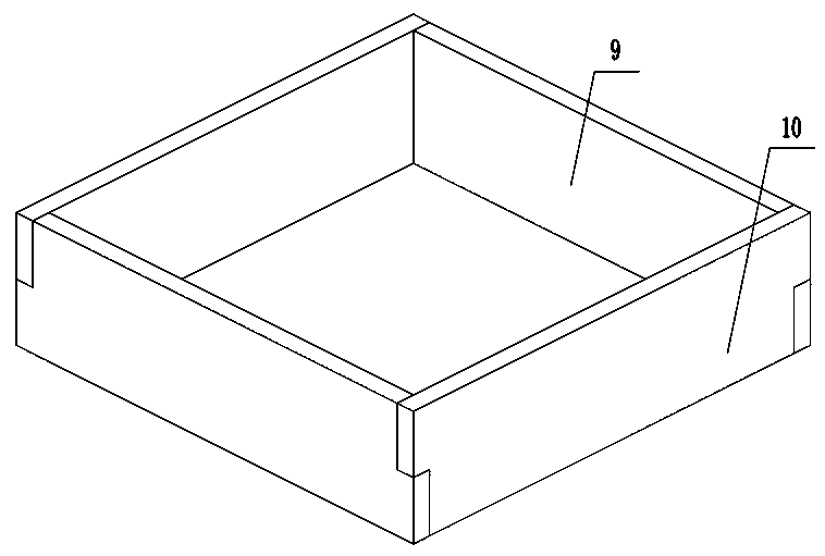
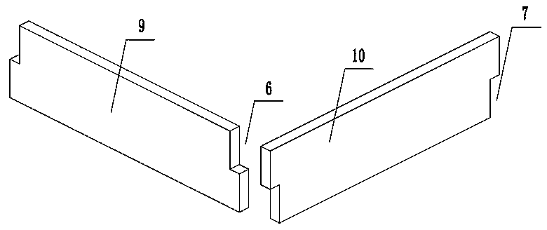
[0035] The U-shaped slots 3 on both sides of the foundation length and width direction of the platform are respectively provided with a prefabricated panel 9 and a prefabricated panel 2 10, and the adjacent prefabricated panels 9 and 2 are embedded with each other. Cover to form a board membrane, and the sides of the board membrane are horizontally provided with square wood 5 to clamp the prefabricated board one 9 and the prefabricated board two 10;

[0036] A steel pipe 4 is arranged between the square timber 5 and the side wall of the foundation pit 1 for support.

[003...

Embodiment 2

[0051] This embodiment is basically the same as Embodiment 1, and the similarities will not be described again. The difference is that the steel pipe 4 is not provided in this embodiment, and the square wood 5 can be directly used to support the board membrane.

Embodiment 3

[0053] This embodiment is basically the same as Embodiment 1, and the similarities will not be repeated. The difference is that square wood 5 is not provided in this embodiment, and steel pipe 4 can be directly used to support the board membrane, that is, one end of steel pipe 4 rests on the On the prefabricated slab, the other end is against the side wall of the foundation pit 1 .


PUM


Abstract

The invention relates to a precast slab formwork nesting connection structure. The structure comprises a foundation pit, a cushion layer arranged at the bottom of the foundation pit and a cap foundation arranged on the cushion layer, wherein U-shaped clamping grooves are formed in the peripheral sides of the cap foundation and in the upper plane of the cushion layer; precast slabs I and precast slabs II are arranged correspondingly in the U-shaped clamping grooves in the two sides of the cap foundation in the length and width directions, the adjacent precast slabs I and precast slabs II are mutually nested to form a slab formwork, and square timbers are arranged transversely on the periphery of the slab formwork to clamp the precast slabs I and the precast slabs II; steel pipes are arranged between the square timbers and the side walls of the foundation pit for support. The precast slabs are in nested connection by staggered joints to form the slab formwork, internal hoop force is formed by nested connection of the slab formwork under the action of pressure of backfill soil outside the defined shape of the slab formwork, so that a stable stress system is formed, the construction process is simple and convenient, and a good supporting structure for a cap formwork can be formed.

Description

technical field [0001] The invention relates to the technical field of building templates, in particular to a prefabricated board membrane nested connection structure and a construction method. Background technique [0002] In the context of slowing domestic economic development, the construction industry is also moving towards high-quality, environmentally friendly, and energy-saving trends; prefabricated building construction, as a sustainable construction method for future construction projects, will gradually replace the current traditional The method of on-site construction work. [0003] In the construction process of the foundation cap, the traditional construction method is to use brick tire formwork to enclose the shape designed on the drawing, and the brick membrane is to use bricks to make formwork to replace the wooden formwork that cannot be constructed. In actual construction, there will often be a phenomenon that 3 to 5 masons in the foundation pit of a found...

Claims


Application Information

Patent Timeline
IPC IPC(8): E02D27/00
CPCE02D27/00
Inventor 苏秀赵腾飞
Owner SHANGHAI BAOYE GRP CORP
Learn More