Anti-floating anchor rod waterproof treatment structure and installation method thereof

An anti-floating anchor and waterproof treatment technology, which is applied in infrastructure engineering, protection devices, sheet pile walls, etc., can solve problems such as loss of waterproof function and groundwater leakage, and achieve enhanced occlusal effect, enhanced waterproofing, and increased contact area. Effect

Active Publication Date: 2020-08-14
湖北卓宝科技有限公司 +1
View PDF4 Cites 1 Cited by
  • Summary
  • Abstract
  • Description
  • Claims
  • Application Information

AI Technical Summary

Problems solved by technology

[0003] Due to the change of the groundwater level, the underground structure (cushion, floor) has a slight displacement. Since the junction of the anti-floating anchor rod and the membrane waterproof layer is connected to form a whole during construction, only the junction is sealed with a sealing material. Treatment, once the groundwater level rises, the underground structural slab floats, dislocation of the anti-floating anchor rod and the structural slab, resulting in the separation of the joint between the anti-floating anchor rod and the waterproof layer, causing the part to lose its waterproof function, and eventually groundwater seepage occurs. leak

Method used


Image

  • Anti-floating anchor rod waterproof treatment structure and installation method thereof
  • Anti-floating anchor rod waterproof treatment structure and installation method thereof
  • Anti-floating anchor rod waterproof treatment structure and installation method thereof

Examples


Embodiment Construction

[0037] Embodiments of the present invention are described in detail below, examples of which are shown in the drawings, wherein the same or similar reference numerals designate the same or similar elements or elements having the same or similar functions throughout. The embodiments described below by referring to the figures are exemplary and are intended to explain the present invention and should not be construed as limiting the present invention.

[0038] In describing the present invention, it should be understood that the terms "length", "width", "upper", "lower", "front", "rear", "left", "right", "vertical", The orientation or positional relationship indicated by "horizontal", "top", "bottom", "inner", "outer", etc. are based on the orientation or positional relationship shown in the drawings, and are only for the convenience of describing the present invention and simplifying the description, rather than Nothing indicating or implying that a referenced device or element...


PUM


Abstract

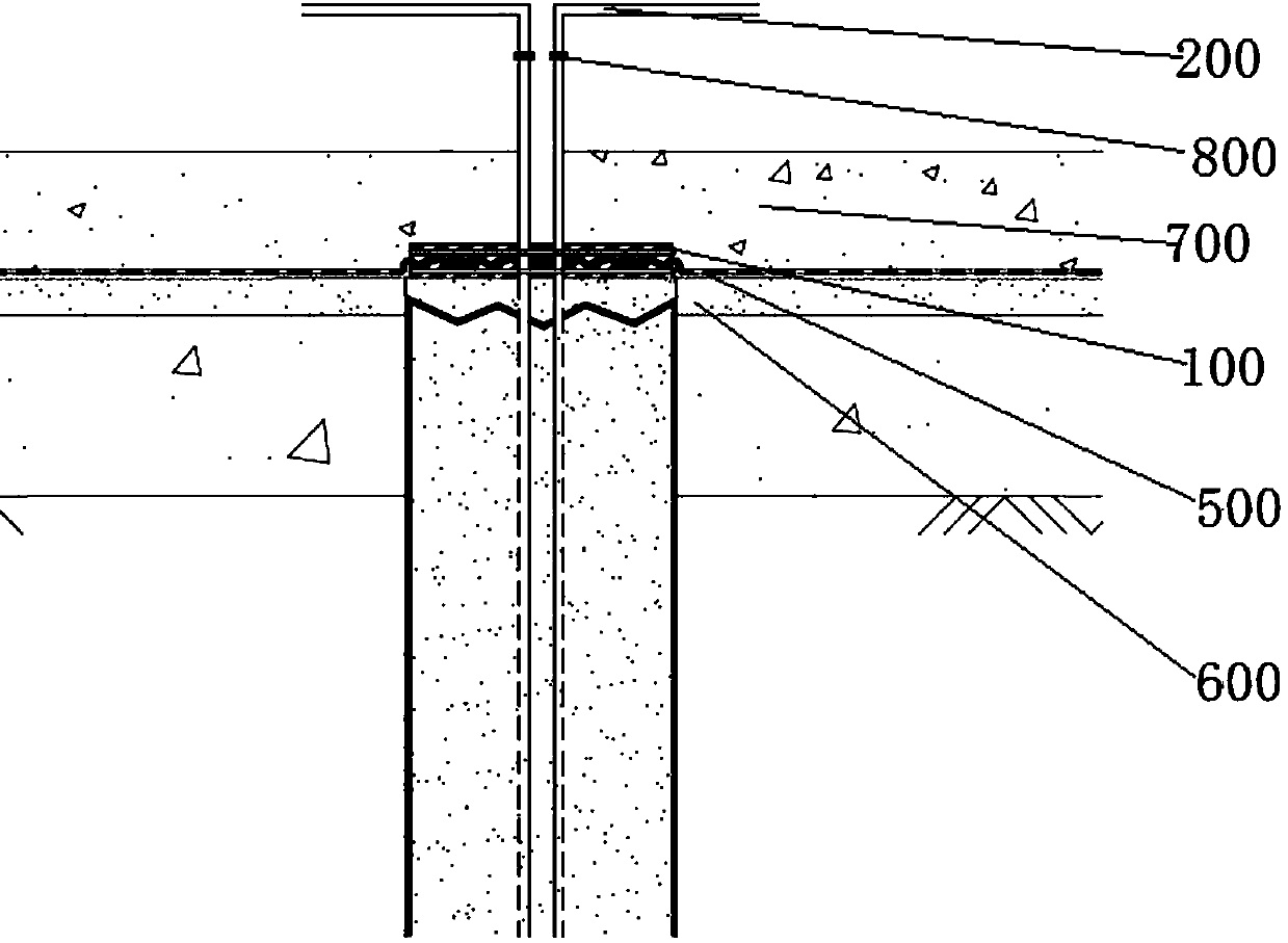
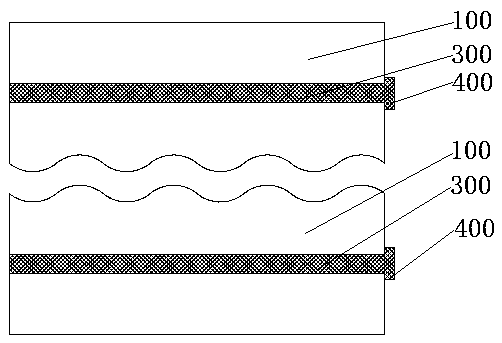
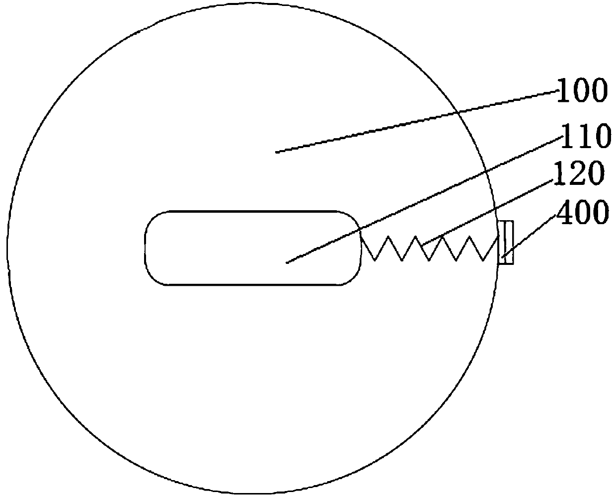
The invention belongs to the technical field of building construction, and relates to an anti-floating anchor rod waterproof treatment structure. The anti-floating anchor rod waterproof treatment structure comprises two buckled and compacted fixing plates, fixing loops, lock catches and waterproof rolls, wherein a through hole allowing an anti-floating anchor rod to penetrate is formed by the twofixing plates; the fixing loops are installed on the side walls of the fixing plates and used for clamping the fixing plates to enable the fixing plates to hold and wrap the anti-floating anchor rod;the lock catches are installed on the end parts of the fixing loops and used for adjusting the clamping degree of the fixing plates to the anti-floating anchor rod; and the waterproof rolls are arranged between the two fixing plates and used for preventing underground water from permeating from contact surfaces of the two fixing plates, and the mutual contact surfaces of the two fixing plates arein a wave shape. The anti-floating anchor rod waterproof treatment structure has the advantages that underground water leakage caused by dislocation of a joint parts of the anti-floating anchor rod and a waterproof layer can be prevented, so that the leakage risk and waterproof maintenance cost of buildings are reduced, and the service life of the buildings is ensured.

Description

technical field [0001] The invention belongs to the technical field of building construction, and relates to an anti-floating anchor rod waterproof treatment structure and an installation method thereof. Background technique [0002] refer to Figure 4 At this stage, most of the underground structures of construction projects will be equipped with anti-floating anchor rods, which are mainly structural components set up to resist the upward displacement of the buildings above them. The component is connected with the basement floor. On the original foundation, the anti-floating anchor is constructed first, the concrete cushion is poured, and the membrane waterproof layer is constructed on the concrete cushion. When the waterproof membrane is constructed to the position of the anti-floating anchor, it is necessary Cut off the overlapping position of the waterproof membrane and the anti-floating anchor, so that the anti-floating anchor can pass through the waterproof membrane, ...

Claims


Application Information

Patent Timeline
Patent Type & Authority Applications(China)
IPC IPC(8): E02D31/02E02D5/74E02D31/12
CPCE02D5/74E02D31/02E02D31/025E02D31/12E02D2300/0001E02D2450/106E02D2600/30
Inventor 黄斯超
Owner 湖北卓宝科技有限公司
Why Eureka
Try Eureka