Cable winding tool

A cable winding and cable technology, which is applied in the directions of transportation and packaging, conveying filamentous materials, thin material processing, etc., can solve the problems of high labor intensity, achieve the effects of reducing labor intensity, improving versatility, and realizing automatic control

Pending Publication Date: 2021-04-16
HENAN PINGGAO ELECTRIC +2
View PDF19 Cites 0 Cited by
  • Summary
  • Abstract
  • Description
  • Claims
  • Application Information

AI Technical Summary

Problems solved by technology

[0004] The purpose of the present invention is to provide a cable winding tool to solve the technical problem of labor-intensive manual coiling of cables in the prior art

Method used


Image

  • Cable winding tool
  • Cable winding tool
  • Cable winding tool

Examples


Embodiment 1

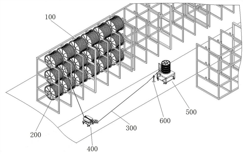
[0076] Such as Figure 1 to Figure 14 As shown, when the cable winding tool is in use, the cable 300 on the large cable reel 200 on the shelf 100 is dragged down, cut and wound at a fixed length.

[0077] The cable winding tool includes a cable dragging device 400 and a cable winding device 500 sequentially arranged along the conveying direction of the cable 300, and also includes a length measuring device 600 between them. The cable dragging device 400 is used to drag the cable 300 from the large cable reel 200, the length measuring device 600 is used to measure the length of the cable 300, and the cable winding device 500 is used to wind the cable 300. The cable 300 is wound onto the reel of the cable winding device 500 .

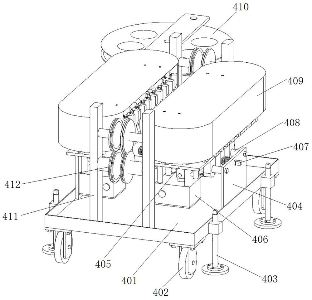
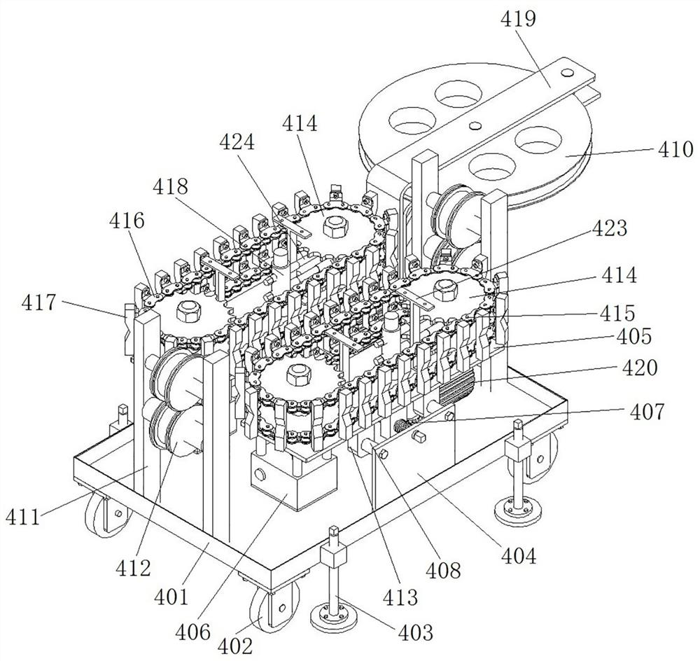
[0078] The structure of the cable dragging device 400 is as Figure 2 to Figure 10 As shown, the cable dragging device 400 is used to drag the cable 300. Since the large cable reel 200 on the shelf 100 is heavy in weight, it requires a large dragging fo...

specific Embodiment 2

[0102] The difference from Embodiment 1 lies in the cable winding device. Such as Figure 15 to Figure 18 As shown, the cable winding device 700 includes a frame 701, on which a motor, a friction clutch, a flange, a guide cylinder, etc. are installed, and its structure is consistent with that of the cable winding device in Embodiment 1, and will not be described in this embodiment. Let's go into more detail. A main support 702 is placed on the flange, and the structure of the main support 702 is as follows Figure 17As shown, the main support 702 includes a bottom support 7021. The bottom support 7021 includes two rings arranged coaxially and a support rod connecting the two rings. A cone 7022 is fixed in the middle of the bottom support 7021. The cone 7022 is narrow at the top and wide at the bottom. The structure has a hole in the middle for the guide cylinder to penetrate to radially position the cone 7022. The top of the cone 7022 is fixed with a square rod 7023, the sq...

specific Embodiment 3

[0109] In Embodiment 1, the supporting rod in the winding reel in the cable winding device realizes the winding of multiple cables of different specifications and types. In this embodiment, the support rods in the winding reel can be canceled, and the reel only winds cables of one specification and type.


PUM


Abstract

The invention relates to a cable winding tool. The cable winding tool comprises a cable dragging device used for dragging a cable on a goods shelf. A channel for the cable to pass through is formed in the cable dragging device. The cable dragging device comprises a clamping mechanism used for clamping the cable in the channel and continuously dragging the cable. The cable winding tool further comprises a cable winding device used for winding the cable dragged out by the cable dragging device. The cable winding device comprises a wire spool and further comprises a motor for driving the wire spool to rotate to wind the cable. The cable winding tool further comprises a length metering device. The length metering device comprises a measuring wheel. The measuring wheel is attached to the cable in the using process and driven by the cable to rotate. The length metering device further comprises a counter used in cooperation with the measuring wheel. The length metering device is located between the cable dragging device and the cable winding device. By means of cooperation among the three devices, automatic dragging, winding and metering of the cable can be achieved, automatic control is achieved, and labor intensity is reduced.

Description

technical field [0001] The invention relates to a cable winding tool. Background technique [0002] The high-voltage circuit breaker product is an open switch product. The high-voltage circuit breaker can not only cut off or close the no-load and load current in the high-voltage circuit, play the role of relay protection device when the system fails, but also cut off the overload current and Short circuit current, with a fairly complete arc extinguishing structure and sufficient current breaking capacity. The secondary circuit that plays a control role in the high-voltage circuit breaker is relatively complicated, and there are many types and specifications of cables used. Each power station needs cables of several specifications. [0003] In the prior art, the whole cable is stored on the three-dimensional shelf in the warehouse, and the rotating shaft in the middle of the cable tray is rotated and installed on the three-dimensional shelf. At present, the method of interce...

Claims


Application Information

Patent Timeline
Patent Type & Authority Applications(China)
IPC IPC(8): B65H51/32B65H51/18B65H57/14B65H57/12B65H54/547B65H54/32B65H61/00B65H75/18
Inventor 李宇鹏师丽芳张润杰徐卫东张良杰刘德良姚灿江王巧红赵维全蔡东苗雷宗昌钟荣松徐刚赵文杰田利忠王福亚张任孙玉洲石治中李竞赵子龙
Owner HENAN PINGGAO ELECTRIC
Why Eureka
Try Eureka