Suspending device for mounting industrial gas pipeline

A pipeline installation and industrial gas technology, applied in the direction of pipeline brackets, pipe components, pipes/pipe joints/pipe fittings, etc., can solve the problems of poor vibration buffering effect, improve buffering effect, avoid stability and firmness, and increase adsorption The effect of the bonding effect

Inactive Publication Date: 2020-08-14
赵艳
View PDF11 Cites 4 Cited by
  • Summary
  • Abstract
  • Description
  • Claims
  • Application Information

AI Technical Summary

Problems solved by technology

[0004] Based on the technical problem that the suspension mechanism has poor buffering effect on the mechanical vibration of the gas pipeline in the prior art, the present invention proposes a suspension device for industrial gas pipeline installation

Method used


Image

  • Suspending device for mounting industrial gas pipeline
  • Suspending device for mounting industrial gas pipeline
  • Suspending device for mounting industrial gas pipeline

Examples


Embodiment 1

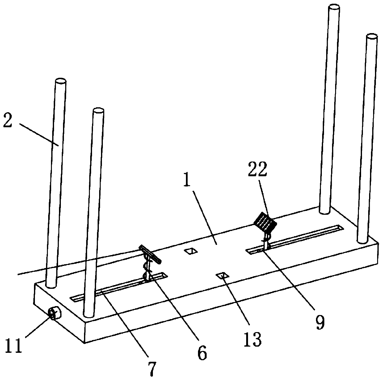
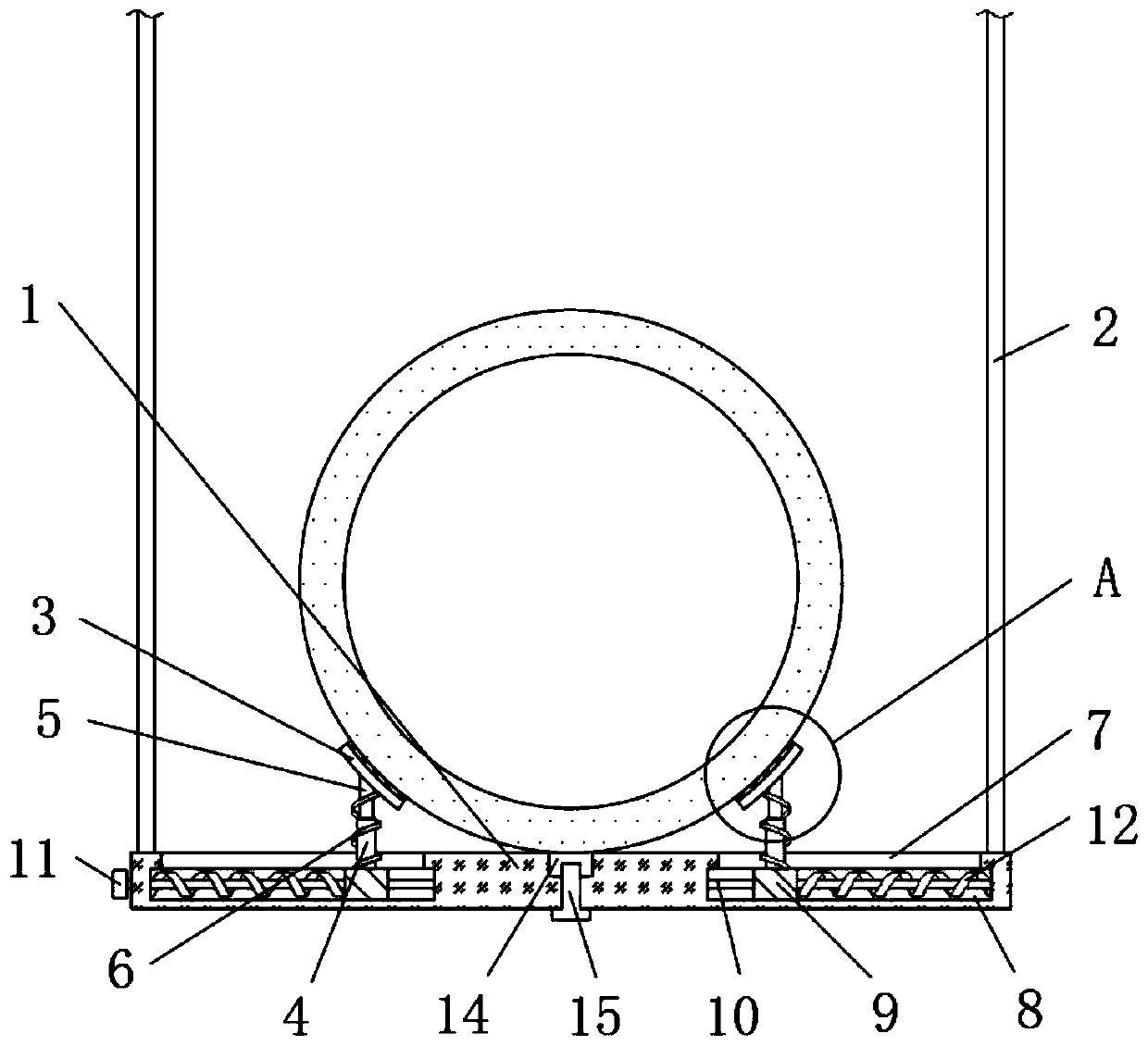
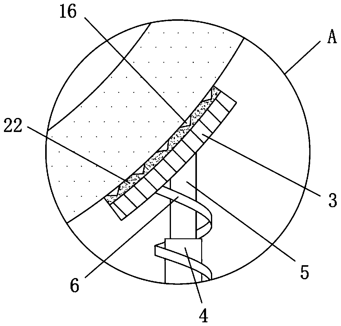
[0028] refer to Figure 1-3 , a suspension device for industrial gas pipeline installation, comprising a support frame 1 placed horizontally, fixing parts 2 are fixed on both sides of the top of the support frame 1, and a gas pipeline is arranged on the top of the support frame 1, and the top of the support frame 1 is located Both sides of the gas pipeline are provided with a clamping piece 3, and the side of the clamping piece 3 close to the gas pipeline is fixed with a rubber pad 22, the clamping piece 3 is inclined downward toward the side close to the gas pipeline, and the clamping piece 3 The side close to the gas pipeline is arranged in an arc-shaped structure. A sleeve 4 is fixed at the position corresponding to the top of the support frame 1 and the clamping piece 3, and the inner wall of the sleeve 4 is slidingly connected with a sleeve rod 5. The top end of the sleeve rod 5 is connected to the clamp. The bottoms of the holders 3 are fixedly connected, and a first spr...

Embodiment 2

[0036] refer to Figure 4-5 , a suspension device for industrial gas pipeline installation, the middle positions of both sides of the outer wall of the top of the support frame 1 are fixed with a fixed base 17, and the two ends of the top of the fixed base 17 and the fixed part 2 are fixedly connected with a second obliquely arranged Three springs 18, the top outer wall of the support frame 1 is located on both sides of the draw-in groove 13 and is provided with a storage groove 19, and the side of the bottom inner wall of the storage groove 19 close to the draw-in groove 13 is connected with an auxiliary support plate 20 by torsion spring rotation, and the auxiliary support plate A fourth spring 21 is fixedly connected between the bottom of 20 and the bottom inner wall of the receiving groove 19 .

[0037] During use, the bottoms of the two third springs 18 are connected to the fixing seat 17 on the top of the support frame 1, thereby increasing the fixed point between the to...


PUM


Abstract

The invention belongs to the technical field of industrial gas pipelines, and particularly provides a suspending device for mounting an industrial gas pipeline. The following scheme is provided currently to solve the problem that in the prior art, the effect of a suspending mechanism for buffering mechanical vibration of the gas pipeline is poor. The suspending device comprises a horizontally-putsupporting frame. Fixing parts are fixed to the two sides of the top of the supporting frame, the gas pipeline is arranged on the top of the supporting frame, clamping parts are arranged at the positions, on the two sides of the gas pipeline, of the top of the supporting frame, rubber cushions are fixed to the sides, close to the gas pipeline, of the clamping parts, and the clamping parts are inclined downwards to the sides close to the gas pipeline. In the suspending device, the gas pipeline is arranged on the supporting frame, the mechanical vibration is dispersed through the inclined clamping parts, the mechanical vibration in the vertical direction is buffered through first springs, the mechanical vibration in the horizontal direction is buffered through second springs, and therefore the effect of the whole suspending mechanism for buffering the mechanical vibration of the gas pipeline is improved.

Description

technical field [0001] The invention relates to the technical field of industrial gas pipelines, in particular to a suspension device for installing industrial gas pipelines. Background technique [0002] Industry mainly refers to the industry or project of raw material collection and product processing and manufacturing, which provides raw materials, fuel and power for itself and other departments of the national economy, and provides industrial consumer goods for people's material and cultural life. The industrial production process will require a lot of energy, gas Function is a commonly used method. Generally, the required gas is guided to the corresponding equipment through the gas pipeline. [0003] The gas pipeline layout in the industrial production process is either buried underground or placed indoors. In the indoor environment, the gas pipeline is generally arranged above the room by means of suspension, and the layout position of the gas pipeline is often arrange...

Claims


Application Information

Patent Timeline
Patent Type & Authority Applications(China)
IPC IPC(8): F16L3/02F16L55/035
CPCF16L3/02F16L55/035
Inventor 赵艳
Owner 赵艳
Why Eureka
Try Eureka