Over fire air device of boiler

A technology of overfired air and boilers, which is applied in the direction of combustion methods, air supply adjustment, and combustion control. It can solve problems such as high-temperature corrosion of boilers, delayed combustion, and difficulty in adjustment, so as to avoid thermal corrosion, reduce skewed burning, and meet The effect of flexible adjustment

Pending Publication Date: 2020-08-14
JIANGSU SUNCO BOILER
View PDF0 Cites 2 Cited by
  • Summary
  • Abstract
  • Description
  • Claims
  • Application Information

AI Technical Summary

Problems solved by technology

[0003] The current overburning air device mostly adopts the coupling structure of internal central DC air and external swirling air. A single DC central air cannot cover the width direction of the boiler. The coupled flow of external swirling air and central DC air makes the penetration of the overburning air Not strong enough
It is common to have a large amount of overfired air, insufficient penetration in the depth direction of the boiler furnace and insufficient coverage in the width of the furnace, which will easily cause delayed combustion of unburned carbon particles and CO, resulting in fly ash in the boiler flue gas, high CO, and boiler efficiency. drop and other issues
Existing overfire air devices mostly use hinge transmission mechanism, which is easy to jam and difficult to adjust
[0004] There are also related technologies that use double-layer overfire air nozzles on the overfire air device to meet the needs of penetration, coverage and air staged combustion. The further lack of oxygen in the boiler area will cause problems such as high-temperature corrosion of the boiler, which will bring great economic problems and hidden safety hazards to the operation of the boiler.

Method used


Image

  • Over fire air device of boiler
  • Over fire air device of boiler
  • Over fire air device of boiler

Examples


Embodiment Construction

[0024] In order to make the purposes, technical solutions and advantages of the embodiments of the present invention clearer, the technical solutions in the embodiments of the present invention will be clearly and completely described below with reference to the accompanying drawings in the embodiments of the present invention. Obviously, the described embodiments These are some embodiments of the present invention, but not all embodiments. Based on the embodiments of the present invention, all other embodiments obtained by those of ordinary skill in the art without creative efforts shall fall within the protection scope of the present invention. It should be noted that the embodiments in this application and the feature vectors in the embodiments may be arbitrarily combined with each other unless there is a conflict.

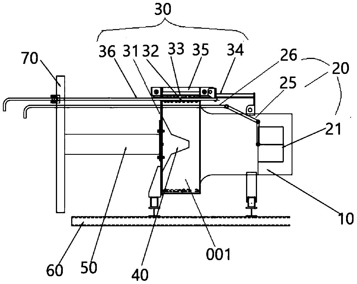
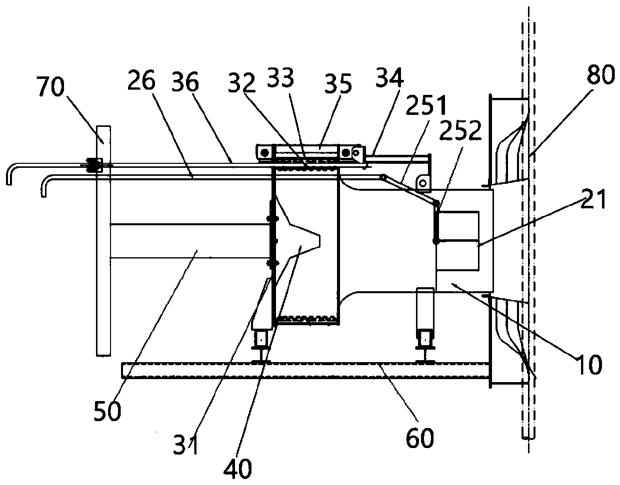
[0025] At present, most of the current burnout air devices adopt the structure of coupling the internal central direct current air and the external swirl wind....


PUM


Abstract

The invention discloses an over fire air device of a boiler. The over fire air device comprises an over fire air nozzle and an air regulator connected to a burner nozzle. The air regulator comprises asupporting plate and an over fire air sleeve, the over fire air is connected to the supporting plate to form an air regulating channel, and the burner nozzle communicates to the air regulating channel; the over fire air sleeve comprises an over fire air barrel arranged on the supporting plate and a sleeve baffle plate arranged on the over fire air barrel in a sleeving manner, an air inlet of theair regulating channel is formed between the sleeve baffle plate and the supporting plate, and the sleeve baffle plate can slide relative to the over fire air barrel to adjust the aperture of the airinlet of the air regulating channel; and the over fire air barrel is a centrosymmetric flow equalizing barrel. The over fire air device can guarantee good penetrate and coverage of over fire air and guarantee that unburned carbon particles and CO in the upper part of a hearth burn thoroughly fully and timely under the circumstance of a relatively small over fire air quantity to reduce inclined deviant combustion of the boiler, so that conditions of hot corrosion due to local overheating of the boiler and the like are avoided.

Description

technical field [0001] The invention relates to the technical field of pulverized coal boiler combustion, in particular to an exhaust air device. Background technique [0002] In the context of increasingly strict national environmental protection policies, environmental protection emission standards have been gradually raised. In order to reduce the emission of nitrogen oxides in NOx coal-fired power plants, the combustion boiler generally adopts the staged combustion method. Axial Air Staged Combustion (OFA) technology is the most effective staged combustion technology, and the overburning air device is one of the most important equipment of this technology. [0003] At present, most of the current burnout air devices adopt the structure of coupling the internal central direct current air and the external swirl wind. A single direct current central air cannot cover the width direction of the boiler, and the coupled flow of the external swirling air and the central direct ...

Claims


Application Information

Patent Timeline
Patent Type & Authority Applications(China)
IPC IPC(8): F23C7/00F23L9/00F23N3/00
CPCF23C7/00F23C2900/06041F23L9/00F23N3/007
Inventor 蔡小峰陈梅芳
Owner JIANGSU SUNCO BOILER
Why Eureka
Try Eureka